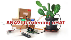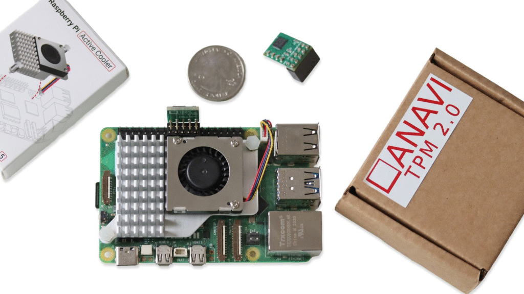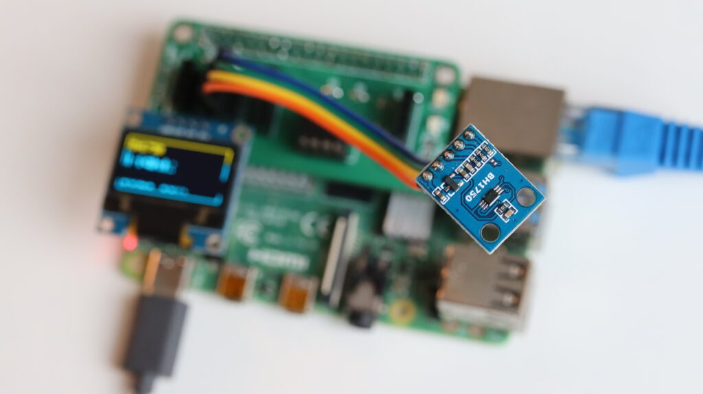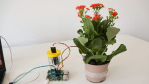
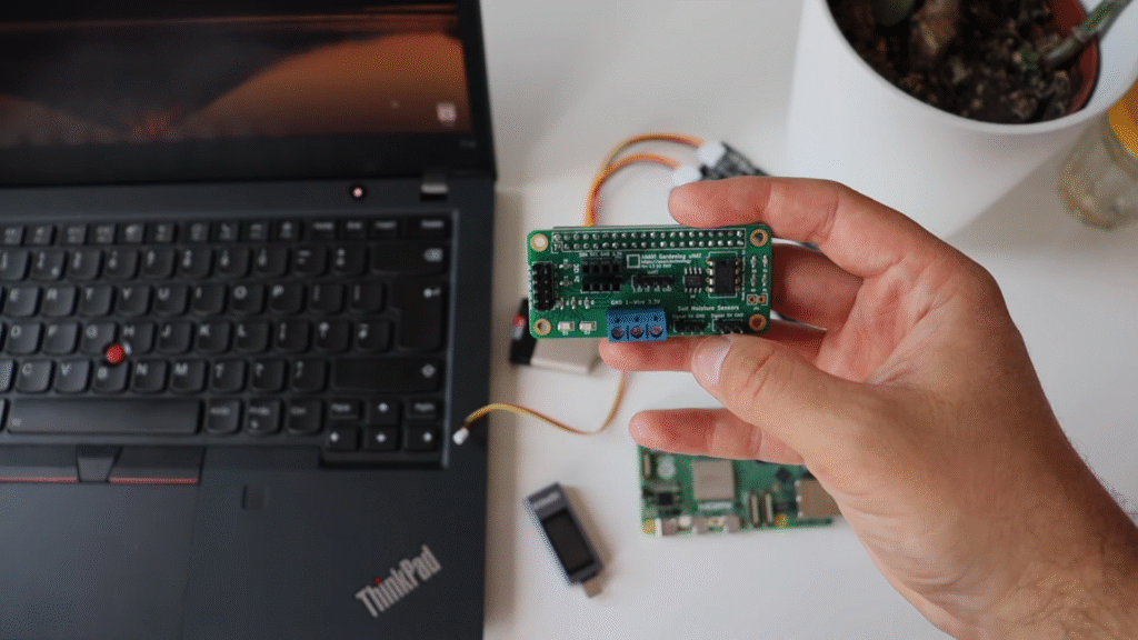
If you have ever wanted to turn your Raspberry Pi into a smart gardening assistant, our ANAVI Gardening uHAT is a simple, low-cost way to get started. This open source add-on board makes it easy to monitor and care for your plants with sensors for soil moisture, temperature, humidity, barometric pressure, and light. Best of all, there is no soldering, special tools, or complicated setup. Just plug the board into your Raspberry Pi with your bare hands, follow the user manual, and you are ready to go. First introduced in 2021 through a successful Crowd Supply campaign, the ANAVI Gardening uHAT is now widely available through distributors such as Mouser Electronics. While the official documentation is based on Raspberry Pi Operating System, the board works with any Raspberry Pi single-board computer and any Linux distribution designed for it. This makes the ANAVI Gardening uHAT not just a hobbyist gadget, but also a versatile tool for anyone experimenting with Internet of Things (IoT), agricultural technology, or embedded Linux.
The Yocto Project Meets Raspberry Pi Gardening
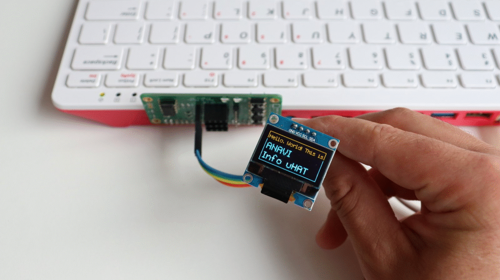
In early 2025, Leon Anavi, the creator of the ANAVI Gardening uHAT, launched a new series of video tutorials on the Yocto Project and OpenEmbedded. These tools, maintained under the Linux Foundation, have become the industry standard for building custom Linux distributions for embedded devices.
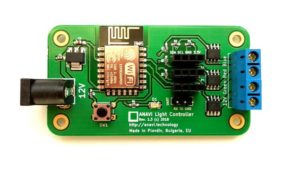
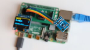
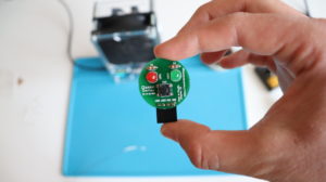
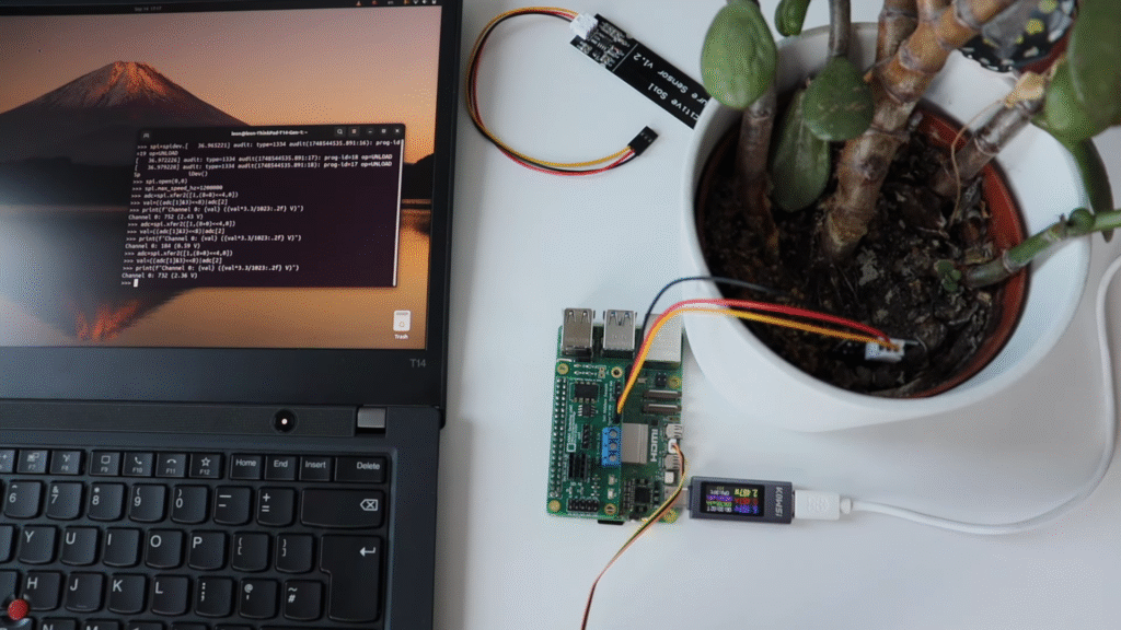
In episode 10 from September 2025, Leon demonstrates how to enable the Serial Peripheral Interface (SPI) on a Raspberry Pi and use it with the Microchip MCP3002 10-bit analog-to-digital converter (ADC) integrated into the ANAVI Gardening uHAT. This allows you to connect analog sensors, such as a capacitive soil moisture sensor, and read their data in real time.
Step-by-Step: Enabling Serial Peripheral Interface with Yocto
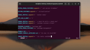
If you want to try the tutorial yourself, here is a simplified version of the steps Leon used in the video. These examples are based on the Yocto Long Term Support (LTS) release Scarthgap and use the meta-raspberrypi board support package (BSP) layer.
- Enable Serial Peripheral Interface support
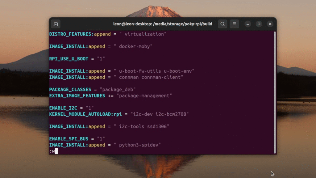
Add the following line to yourconf/local.conf:ENABLE_SPI_BUS = "1" - Include required Python packages
Extend your Linux image with thespidevlibrary (used in the examples), plus some helpful tools:IMAGE_INSTALL:append = " python3-spidev" - Build and flash your image
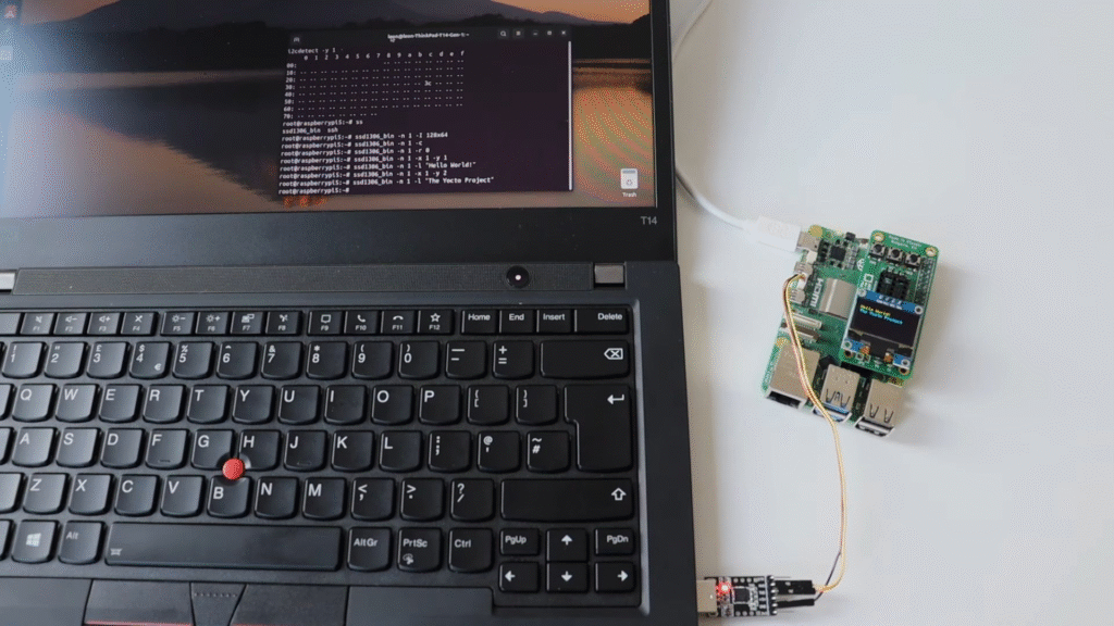
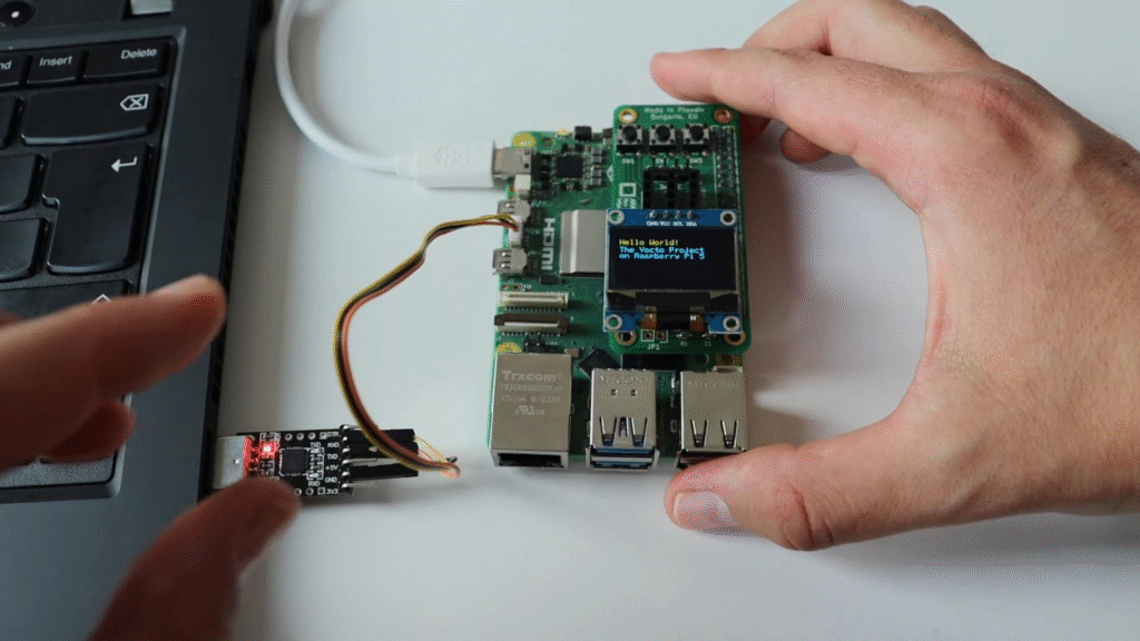
Build thecore-image-base, flash it to a microSD card, and boot your Raspberry Pi. - Run Python code to read sensor values
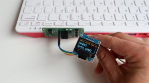
Open a Python 3 interactive shell and use this example code snippet to start reading data from a capacitive soil moisture sensor through the MCP3002 analog-to-digital converter.

Why This Matters
This combination of ANAVI Gardening uHAT and the Yocto Project is more than just a fun do-it-yourself experiment. It is a hands-on way to learn about:
- Embedded Linux development
- Custom Raspberry Pi distributions
- Practical Internet of Things (IoT) applications in agriculture
For hobbyists, it means you can monitor your houseplants or small garden with open source hardware and software. For professionals, it is a chance to explore how Yocto-powered Linux images can streamline development in real-world embedded projects.