In the world of electronics and IoT, gesture recognition has emerged as a fascinating and practical technology. Whether it’s controlling your favorite gadgets with the wave of a hand or adding a touch of magic to your projects, gesture recognition sensors play a pivotal role. Among the numerous sensors available, the APDS9960 stands out as a versatile and widely used I2C sensor at a very affordable price. In this blog post, we will take you on a journey through the fascinating world of gesture recognition using the APDS9960 sensor on a Raspberry Pi and any of our popular add-on boards: ANAVI Infrared pHAT, ANAVI Light pHAT, ANAVI Gardening uHAT, ANAVI Info uHAT as well as ANAVI Miracle uHAT and ANAVI CO2 uHAT (both of which are in final development).
What is APDS9960?
APDS9960 is an I2C (Inter-Integrated Circuit) sensor produced by Broadcom (formerly Avago Technologies). It is known for its versatility and is commonly used for gesture recognition, proximity sensing, ambient light sensing, and color sensing applications. Gestures are detected at a distance of 10 to 20 cm. The sensor has built-in UV and IR filters for better recognition. Its wide range of applications makes it a favorite choice among electronics enthusiasts, engineers, and hobbyists. Ovewr the years APDS9960 has been integrated in many popular consumer electronic devices, including Samsung Galaxy S5 smartphone.
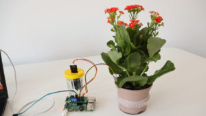
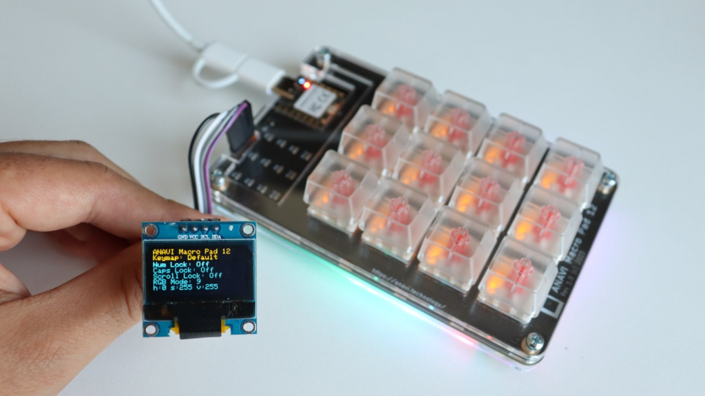
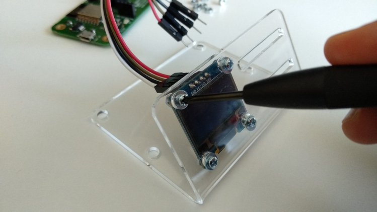
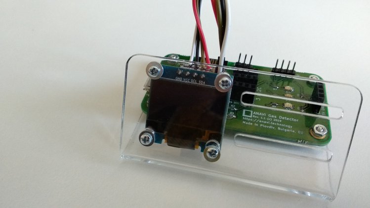
In this tutorial, we will explore how to set up gesture detection on a Raspberry Pi running the Raspberry Pi OS Linux distribution. Specifically, we will use the APDS9960 I2C sensor connected to a Raspberry Pi uHAT (add-on board) and a mini OLED SSD1306 I2C yellow-blue display.
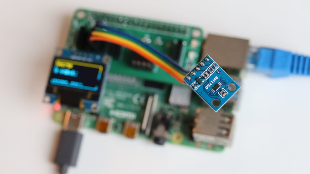
🔌 Hardware Setup
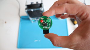
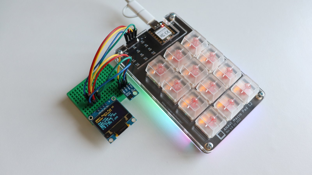
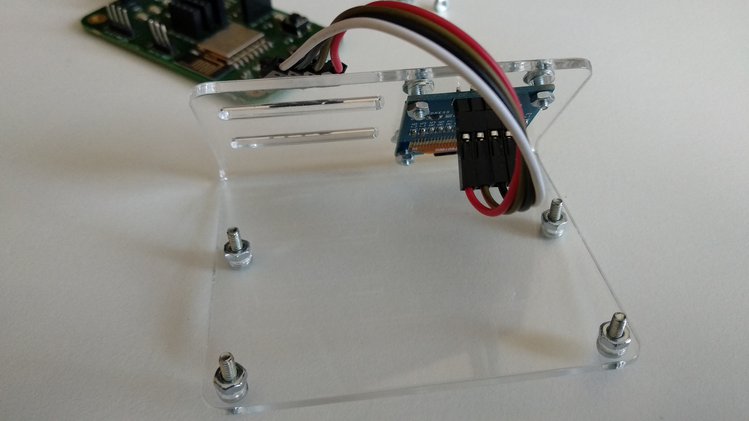
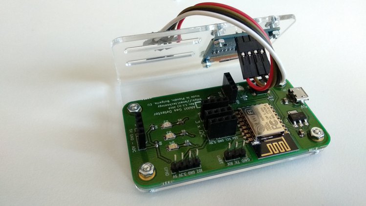
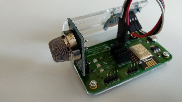
Both APDS9960 sensor and the mini yellow-blue SSD1306 OLED display rely on the serial communication protocol I2C that allows multiple electronic devices to communicate with each other using only two wires: serial data (SDA) and serial clock (SCL). Raspberry Pi single board computers have two different I2C busses. The primary I2C bus is at GPIO 2 (physical pin 3 for SDA) and GPIO3 (physical pin 6 for SCL). These pins should be used to attach APDS9960 and the mini OLED display to the Raspberry Pi. Also APDS9960 should be connected to 3.3V and GND pins of the Raspberry Pi to be powered. This makes 4 wires in total to attach the sensor. ANAVI HATs (Hardware Attached on Top) for Raspberry Pi offer dedicated slots for I2C sensors. On ANAVI Info uHAT and ANAVI CO2 uHAT there are even dedicated slots for the mini OLED display.
Of course the OLED display is optional and as an alternative we offer a simple command-line Python3 example for APDS9960 which can function without the OLED display.
🖥️ Software Setup
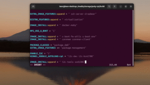
The software setup is straight forward: install Raspberry Pi OS on microSD card, boot your Raspberry Pi and enable I2C using raspi-config. More details are available in the user’s manual for our HATs.
🐍 Python3 Scripts
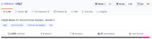
The heart of our demonstration are scripts written in the Python 3 programming language. We’ve tailored the script to work seamlessly with Raspberry Pi OS, but it should also run smoothly on any other GNU Linux distribution. These scripts rely on popular Python3 libraries like PIL and Luma OLED. You can find the source code on GitHub for reference and further experimentation:
https://github.com/AnaviTechnology/anavi-examples/tree/master/sensors/APDS-9960/python
There are two different Python 3 scripts to demonstrate APDS9960 gesture detection:
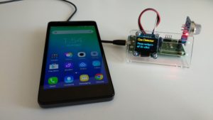
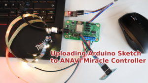
- gesture-oled.py for detecting gestures and showing them on the mini OLED display as in the video
- gesture.py for detecting gesture and printing them in the command-line interface (use this one if don’t have a suitable mini OLED display)
👁️ Real-Time Gesture Detection
Experience the magic as the APDS9960 sensor detects your hand movements, including swipes, taps, and more. Witness how your Raspberry Pi interprets and responds to these gestures in real-time, opening up a world of interactive possibilities. The video provides insights into potential issues you might face during setup and offers practical tips to ensure a seamless experience.
🎓 Conclusion
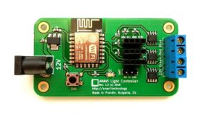
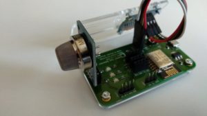
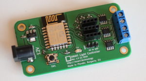
APDS9960 sensor and Raspberry Pi combination offer a compelling glimpse into the exciting world of gesture-based interaction. Instead of using a breadboard and multiple wires it is always easier to rely on one of our add-on boards like ANAVI Infrared pHAT, ANAVI Light pHAT, ANAVI Gardening uHAT, ANAVI Info uHAT, ANAVI Miracle uHAT and ANAVI CO2 uHAT.
So, if you are ready to embark on this exciting journey into gesture recognition technology, grab your Raspberry Pi, APDS9960 sensor, and let’s get started!