AI-Thinker is a leading supplier of IoT wireless products and solutions, including antennas, modules and RF lab service. Since 2017 we have been using AI-Thinker ESP-12E modules with ESP8266 in many of our open source hardware products, including ANAVI Fume Extractor, ANAVI Gas Detector, ANAVI Thermometer, ANAVI Light Controller and ANAVI Miracle Controller.
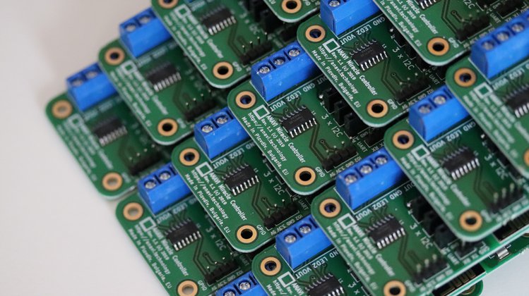
AI Thinker modules with ESP8266
Now, despite the hard times of global chip shortage, AI-Thinker keeps manufacturing and delivering high-quality modules on time. As a trusted supplier through the years, recently we have purchased from AI Thinker enough ESP-12E modules do fulfill the demand and keep making our open source hardware products.
AI Thinker modules with RISC-V microcontroller
Furthermore we stocked ESP-C3-12F modules with Espressif Systems ESP32-C3 Wi-Fi microcontroller based on the open standard instruction set architecture (ISA) RISC-V. ESP-C3-12F are pin to pin compatible with ESP-12E.
AI Thinker ESP32
AI-Thinker is based in Shenzhen, China. The company was founded 10 years ago, in 2012. They also provide LoRaWAN, NB-IoT, Bluetooth and other Wi-Fi modules.
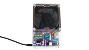
ANAVI Fume Extractor is an open source smart solder smoke absorber useful for makers during soldering. It comes as a do-it-yourself kit. There are 3 types of kits with different sensor modules. ANAVI Fume Extractor is available at Crowd Supply, Mouser and Tindie.
ANAVI Fume Extractor video assembly guidelines
This tutorial explains the exact steps of how to assemble the ANAVI Fume Extractor developer kit which contains all supported peripherals. The whole process can take up to 30-40min. A screwdriver is required. It is highly recommended to watch the video with the assembly guidelines before you start.
Step 1: Peel off the protective films
Each ANAVI Fume Extractor kit contains 4 acrylic enclosures. Peel off the protective films from both sides of all of them. The acrylic enclosure will be clear and transparent once the film is peeled off.
Step 2: PCB
Attach the ANAVI Fume Extractor printed circuit board to the bottom acrylic enclosure with 4 screws and 8 nuts. Add 4 nuts below and 4 nuts above the board.
Step 3: Mini OLED Display
The kit includes 4 M2 screws and nuts as well as appropriate washers. Remove the protective film from the mini I2C OLED display. Carefully attach the display to the front acrylic case as shown in the video. The display is fragile. Don’t fasten the screws too tight!
Step 4: Fan Filter
A couple of fan filters are included in each kit. Attach the 4 M4 screws to the front acrylic enclosure with 4 of the M4 nuts. Place one of the filters. Leave the other one as a replacement.
For long-term maintenance over time the filter must be regularly replaced. There is a huge variety of 80mm fan filters on the market. It is up to you to decide whether to buy carbon or HEPA filters. Various distributors offer appropriate filters, for example Mouser has 80 mm, 45 PPI foam media filters.
Step 5: Fan
Add the acrylic enclosure that separates the fan from the filter. On the side of the fan you will notice a label that indicates the direction of the air flow. Place the 80mm 5V DC fan so that the air will flow through the filter.
Screw the 4 M4 20mm stand-offs to firmly fix the position of the fan.
Step 6 (optional): Light Sensor Module
Owners of a developer kit should add the BH1750 light sensor module to the front acrylic enclosure and fix it with one M4 screw and a nut.
Step 7: Peripherals
Connect peripherals, like the fan and the mini OLED display, to the printed circuit board. There are dedicated connectors for both of them. Pay attention to the labels for I2C on the top of the mini OLED display.
Step 8 (optional): Sensors
Owners of advanced or developer kits should attach:
MQ-135 for indoor air quality
HTU21D I2C sensor module for temperature and humidity
BMP180 I2C sensor module for barometric pressure and temperature.
Step 9: Assemble all acrylic enclosures
Finally, assemble together all acrylic enclosures by fastening 4 M4 nuts on the back of ANAVI Fume Extractor.
On the right side of ANAVI Fume Extractor you will notice a jumper for the WiFi as well as a button to switch the filter on and off. By default the jumper for the WiFi is set to OFF. Move it to ON and power cycle the board if you want to connect ANAVI Fume Extractor to a MQTT broker and IoT platform such as the popular open source system Home Assistant.
To turn ANAVI Fume Extractor on, gently plug an appropriate cable and 5V power supply into the microUSB connector on the left side of the board. The microUSB connector is used only for providing power, no data is transferred. Power supply and microUSB cable are NOT included in any of the kits.
For advanced or developer kits, on the first boot, it is very important to do what is called the “burn-in” procedure for initial calibration of MQ-135 air quality sensor module:
Place ANAVI Fume Extractor with the attached MQ-135 in a room with clean air
Leave it running for at least 24 hours
This has to be done only once when the MQ-135 sensor module is used for the first time. After doing this procedure, on every next boot ANAVI Fume Extractor and MQ-135 will do a quick calibration in a couple of minutes and start working properly.
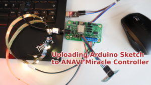
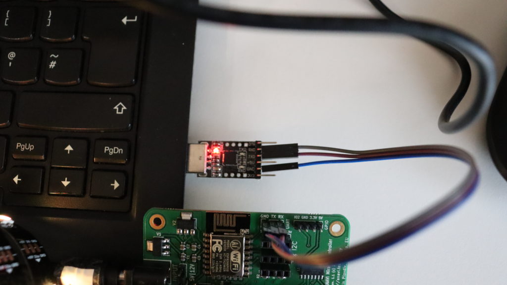
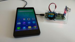
ANAVI Miracle Controller connected with USB to UART cable to a personal computer
Esptool is a free and open source ESP8266 and ESP32 serial bootloader command-line utility. The source code is available at GitHub under GPLv2 license. It is written in Python therefore it is universal and runs on Microsoft Windows, Mac OS and any GNU/Linux distribution (Ubuntu, Debian, Linux Mint, Fedora, CentOS, OpenSUSE, etc). We have already cover it for our other projects in a previous blog post. Today we will focus on ANAVI Miracle Controller although in general the steps are the same.
Installation
As of today, esptool works fine with Python 2.7 or Python 3. Python 2 has been deprecated since January 1, 2020 therefore it is recommended to use esptool with Python 3.
The easiest way to install the latest stable version of esptool is from pypi via pip. The pre-requirements are to have Python and pip installed. Open a terminal and execute the following command:
pip install esptool
Using write_flash argument esptool flashes pre-compiled binary to devices with ESP8266 or ESP32. Here are the exact steps:
NOTE: As of the moment the latest stable version is anavi-miracle-controller-sw-100-20200527.bin. Over the time other version may be released so please make sure you are using the latest and replace the file name accordingly in the command above!
Pretty much the same approach can be used to flash the pre-compiled firmware to any of our dev boards with ESP8266, like ANAVI Fume Extractor, ANAVI Thermometer, ANAVI Gas Detector, etc. Apart from flashing firmware to ESP8266 and ESP32 devices, esptool has a lot of other advanced features which I encourage you to explore. Have a look at the video tutorial and run esptool.py -h to learn more.
Last but not least, huge thanks to the contributors of the open source firmware of ANAVI Miracle Controller: Per Cederqvist, CODeRUS and Daniel Landau. Community always must be priority for any open source project and it is great to see more people involved with ANAVI Miracle Controller!
Esptool is a free and open source ESP8266 and ESP32 serial bootloader command-line utility. The source code is available at GitHub under GPLv2 license. It is written in Python therefore it is universal and runs on Microsoft Windows, Mac OS and any GNU/Linux distribution (Ubuntu, Debian, Linux Mint, Fedora, CentOS, OpenSUSE, etc).
Installation
As of today esptool works fine with Python 2.7 or Python 3. Python 2 has been deprecated since January 1, 2020 therefore it is recommended to use esptool with Python 3.
The easier way to install the latest stable version of esptool is from pypi via pip. Open a terminal and execute the following command:
pip install esptool
Flashing Firmware
Using write_flash argument esptool flashed pre-compiled binary to devices with ESP8266 or ESP32. Here are the exact steps:
Download an appropriate binary for your ESP8266/ESP32 device.
Connect your device to a computer. For example, for ANAVI Thermometer, ANAVI Gas Detector, ANAVI Light Controller and ANAVI Miracle Controller you must use UART to USB debug cable.
Turn on the device in boot mode. For example, on ANAVI Thermometer, ANAVI Gas Detector, ANAVI Light Controller and ANAVI Miracle Controller, press and hold the RESET button and plug the power supply.
All ANAVI Internet of Things with ESP8266/ESP32 combine free and open source software with open source hardware. The firmware is built using Arduino IDE and a pre-compiled binary file is available at GitHub. Follow the links below to identify your ANAVI device and download appropriate binary for the latest stable firmware:
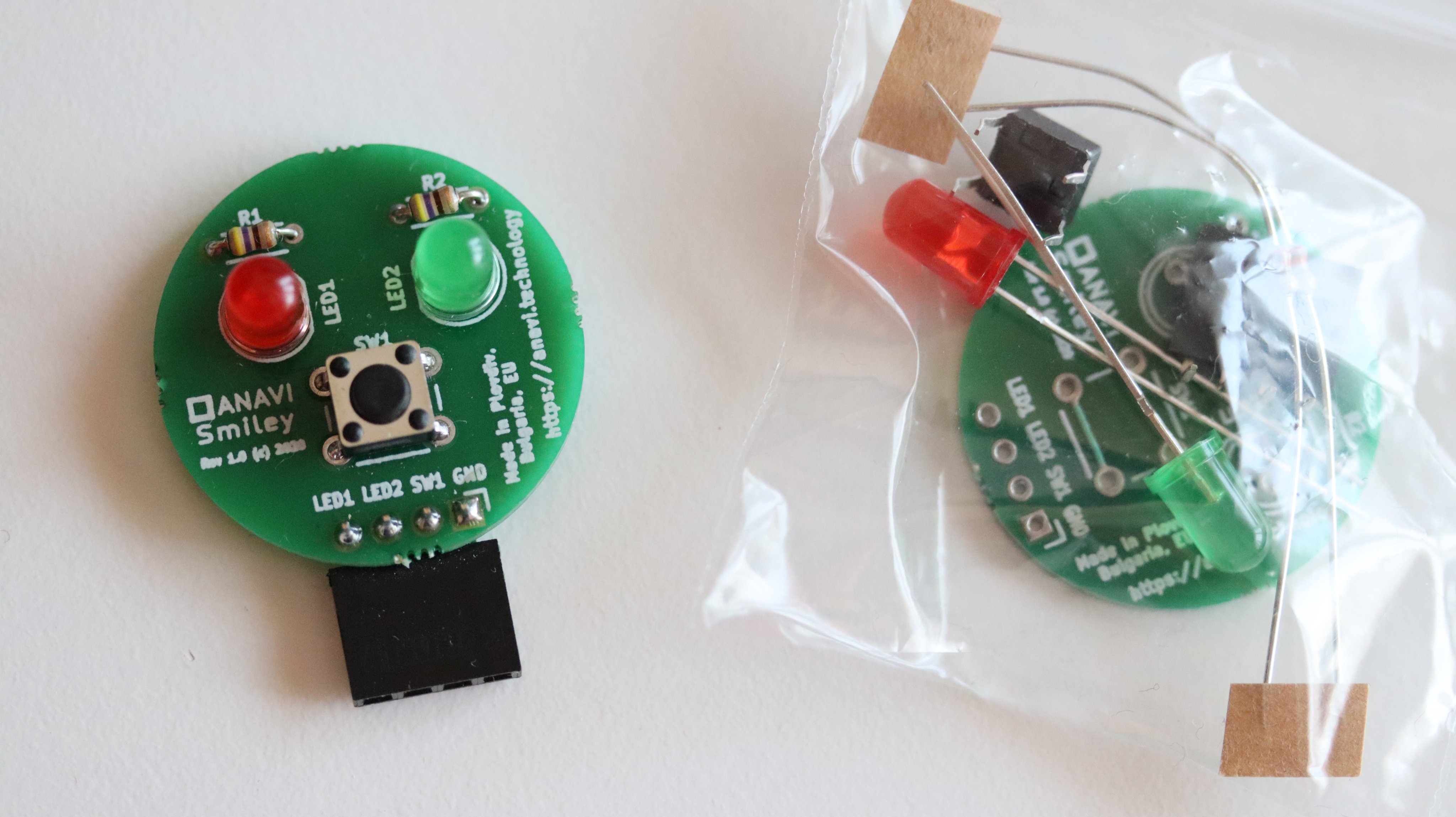
The primary goal of ANAVI Technology Ltd. is to combine open source hardware with free and open source software. So far numerous of our development boards have been certified by the Open Source Hardware Association (OSHWA). In February 2020 a couple new products were also certified: ANAVI Smiley and ANAVI Tag Manager. Both of them have been designed with the free and open source tool KiCad.
A lot of products on the market claim their are open source hardware, however this is not always true. Open Source Hardware certification allows the community to quickly identify hardware that truly complies with the definition of open source hardware. Because of this certification by OSHWA is important for us.
ANAVI Smiley
ANAVI Smiley add-on board for Raspberry Pi as a soldering kit
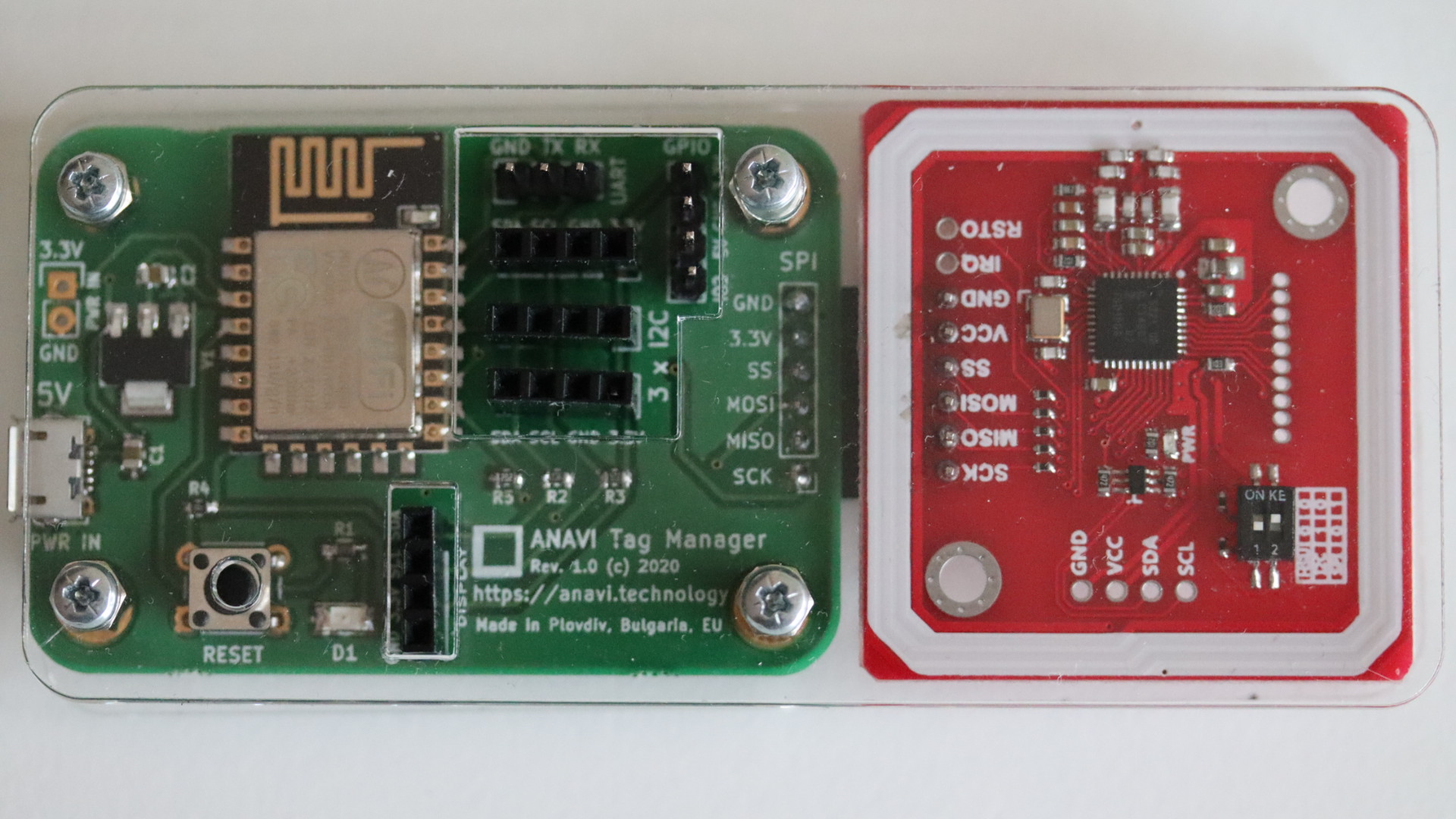
ANAVI Tag Manager with PN532 NFC RFID module and an acrylic enclosure
ANAVI Tag Manager is a WiFi development board for using PN532 NFC RFID module. The board is using ESP8266. It is powered from microUSB connector. There are slots for UART pins, mini OLED display and up to 3 I2C sensor modules. Furthermore there is also an extra GPIO pin for custom automation solutions. ANAVI Tag Manager is useful for various applications with NFC, including smart locks and payment systems. It has been certified by OSHWA with UID BG000062.
Stay tuned for new articles with details about both of these exciting new open source hardware gadgets!
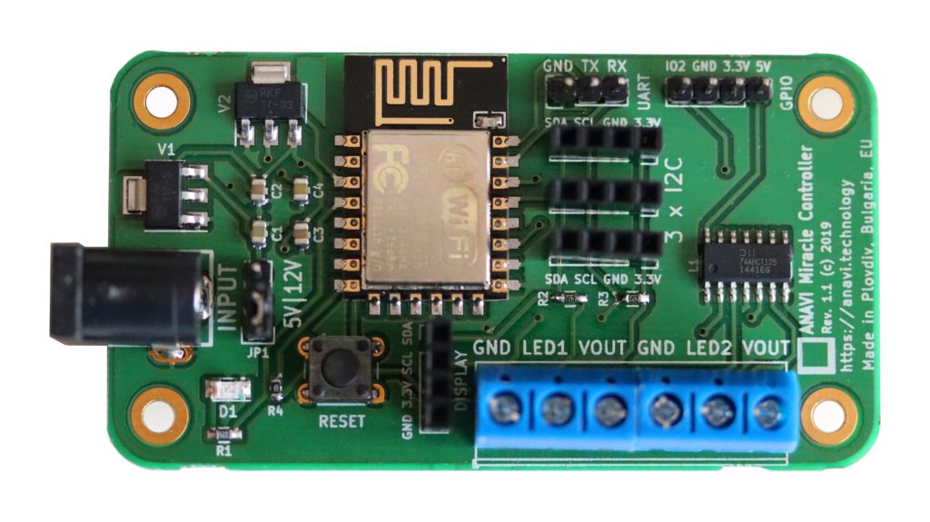
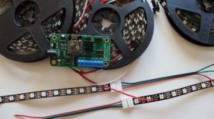
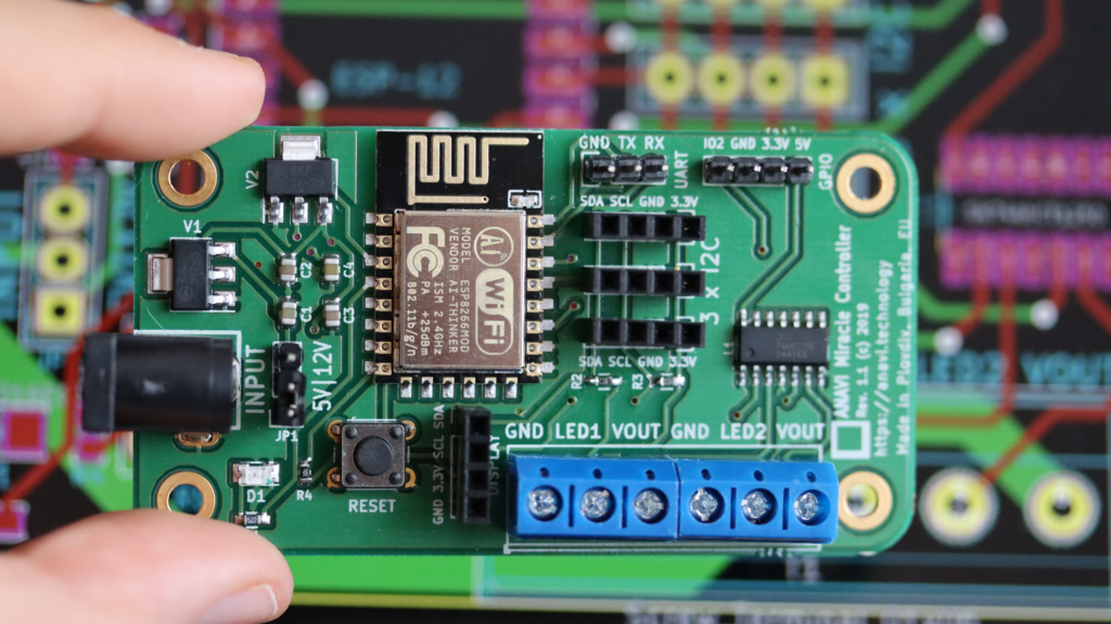
ANAVI Miracle Controller is an ESP8266-powered Wi-Fi dev board to control two 5 V or two 12 V addressable (digital) LED strips like WS2812B, WS2812, WS2811, etc. Furthermore, mini OLED display and up to 3 I2C sensors can be attached. It has been certified by the Open Source Hardware Association.
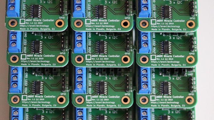
We have already started manufacturing. The first and second batches of boards are ready. Right now we are testing and packaging them. The estimated shipping date remains the same – Mar 30, 2020. In the meantime you can still place pre-orders at the same prices. Crowd Supply will take care of the shipping for all orders placed during the crowdfunding campaign and pre-orders.
ANAVI Miracle Controller is a new entirely open source development board for addressable (digital) LED strips like NeoPixels, WS2812B, WS2811, etc. The major advantages are that you can control two LED strips simultaneously, add a mini OLED display and I2C sensor modules as peripherals. Recently we launched a crowdfunding campaign for it at Crowd Supply.
ANAVI Miracle Controller
ANAVI Miracle Controller is a development board and it is easy to flash a custom firmware on it. The process is very similar as for our other open source project like ANAVI Thermometer, ANAVI Gas Detector and ANAVI Light Controller.
This tutorial explains the exact steps how to compile and upload the default open source Arduino sketch for ANAVI Miracle Controller using Arduino IDE.
Required Hardware
ANAVI Miracle Controller
USB to UART debug cable
Addressable LED strip
Appropriate power supply at 5V or 12V depending on the type of LED strips
Personal computer with MS Widows, Mac OS or GNU/Linux distribution
Optionally a mini OLED display and other peripherals can be attached
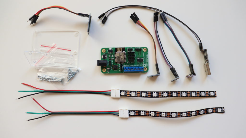
ANAVI Miracle Developer kit
Download Source Code from GitHub
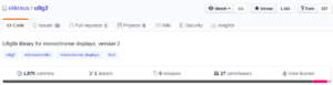
The default firmware of ANAVI Miracle Controller is an open source Arduino sketch. It relies on several popular open source Arduino libraries, including FastLED for controlling addressable LED strips. Clone or download the source code from GitHub.
Connecting UART to USB
Each ANAVI Miracle Controller kit includes a USB to UART debug cable with CP2102. Depending on the operating system on your PC you might be required to install additional drives. It works out of the box on GNU/Linux distributions. As open source enthusiasts we are using it on Ubuntu. Plug the USB in your computer and connect the 3 wires as follows:
ANAVI Miracle Controller
USB to UART Debug Cable
RX
TX
TX
RX
GND
GND
Connecting USB to UART cable to ANAVI Miracle Controller
Download Arduino IDE
Download and install Arduino IDE on your personal computer. It is free and open source software available for MS Windows, Mac OS and GNU/Linux distributions.
Launch Arduino IDE. From File > Open load an Arduino sketch. It can be the default firmware or any other compatible with ANAVI Miracle Controller Arduino sketch.
Configure ESP8266 in Arduino IDE
Go to File > Preferences. Select Settings and in the field Additional Boards Manager URLs add: http://arduino.esp8266.com/stable/package_esp8266com_index.json
From Arduino IDE select Tools > Board: Generic ESP8266 Module. Set the flash size to 4M (1M SPIFFS). The upload speed is 115200. Adjust the exact port of USB to serial debug cable connected to your computer.
In Arduino IDE click Verify/Compile. If there are any errors, please double check that you have installed all required libraries and their exact versions. If the source code compiles successfully, please proceed to to the next step for flashing the firmware.
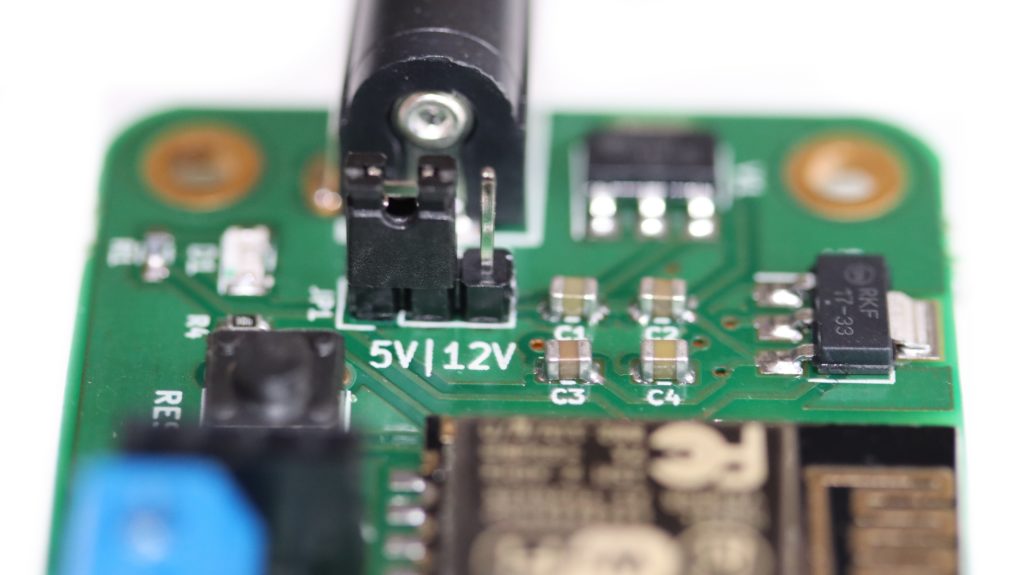
Set the jumper to 5V or 12V depending on the type of addressable LED strip and power supply. Mismatch of the voltage may lead to severe hardware failure.
In Arduino IDE click Upload. Set the jumper on ANAVI Miracle Controller to 5V or 12V depending on your power supply and type of LED strips. The power supply voltage must match the required voltage by the LED strips, for example 5V for NeoPixels and the WS2812B included in all kits. Press and hold the RESET button on ANAVI Miracle Controller. Without releasing the RESET button, plug the power supply in the barrel jack of ANAVI Miracle Controller.
Do NOT release the RESET button until you see in Arduino IDE that the upload is 100% completed!
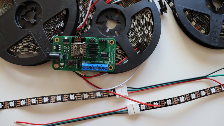
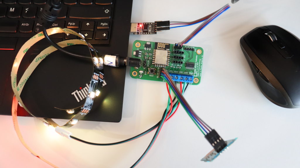
ANAVI Miracle Controller with 2 WS2812B LED strips connected to a laptop using USB to UART cable
How often do you get software or firmware updates for a 2-year-old device? Probably not very often. This is not the case for ANAVI Light Controller! We have a major update of its Arduino sketch for you.
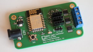
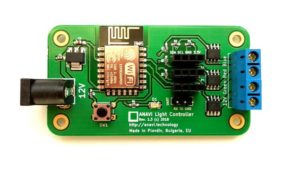
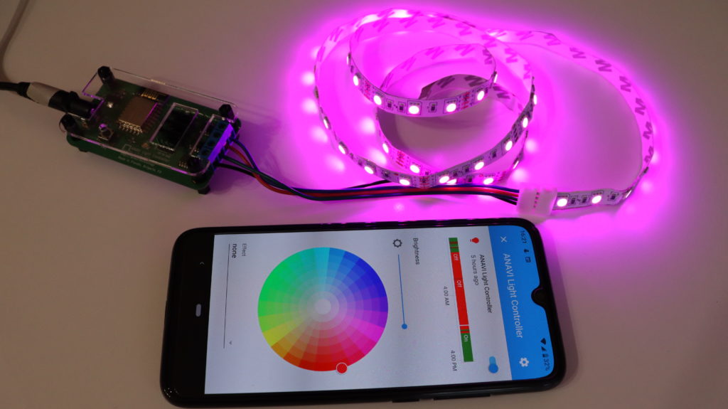
ANAVI Light Controller
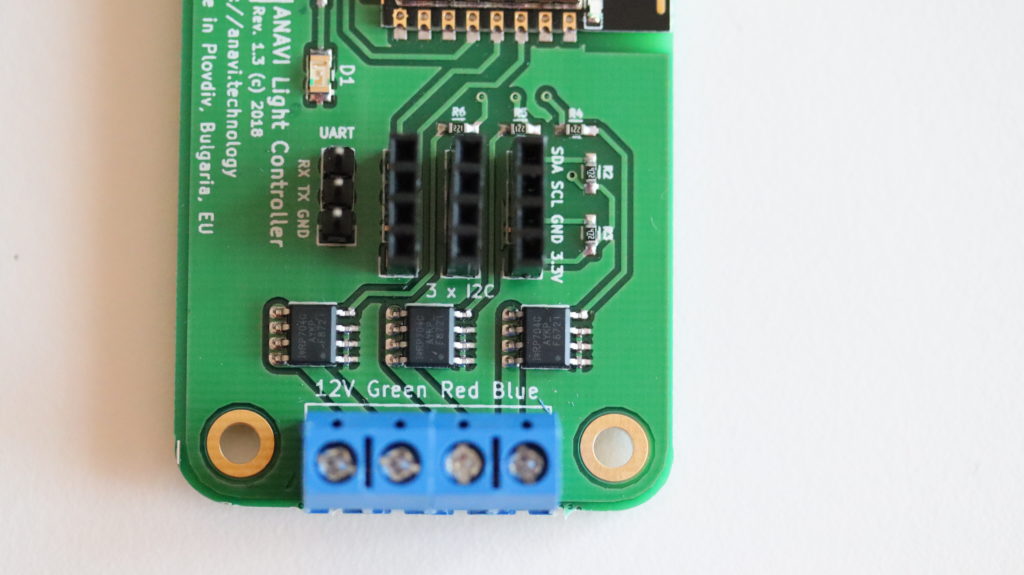
ANAVI Light Controller open source hardware WiFi device for controlling a 12V RGB LED strip. It was brought to life through a crowdfunding campaign at Crowd in 2018. Now is January 2020, so this makes it ~2 years old! A lot of things have changed during this time. ANAVI Light Controller has been certified by Open Source Hardware Association (OSHA) and it now on sale at our distributors: Crowd Supply, Pi Supply and neven.cz.
Terminals for connecting 12V RGB LED strip to ANAVI Light Controller
Support Home Assistant automatic discovery over MQTT
Turn on LED D1 on ANAVI Light Controller if the device is not connected to local WiFi network and needs initial configuration
Wait for a few seconds while LED D1 is blinking immediately after turning on ANAVI Light Controller to allow reset by keeping SW1 pressed
Append the last 5 characters of the machine ID to the WiFi Access Point (AP) to simplify the identification of the ANAVI Light Controller during the initial setup
Support MQTT messages with large payload for reporting back the current state of the RGB LED strips on topic stat/dev-id/color
Add DEBUG macros, disabled by default, if enabled additional debug information will be printed in the serial monitor
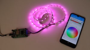
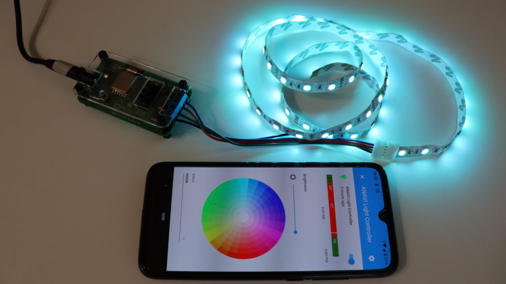
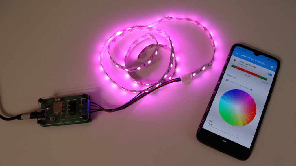
Changing colors of 12V RGB LED strip through Home Assistant using ANAVI Light Controller
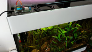
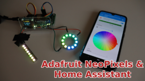
Andrey Kozhevnikov a.k.a. CODeRUS, a talented software engineer and a very skilled maker, used ANAVI Miracle Controller and addressable (digital) LED strips to decorate his Christmas tree and to control it with voice commands through Google Assistant and Home Assistant. Home Assistant is a popular open source platform for home automation. Google Assistant is an artificial intelligence-powered virtual assistant that recognizes speech and voice commands. CODeRUS shared a short video in twitter with the amazing result!
As a small gift for the leading contributor to the Arduino sketch for another of our open source projects, ANAVI Light Controller, we sent one of the first stable prototypes of ANAVI Miracle Controller to CODeRUS. We were sure that he will make something interesting with it. His amazing creativity is always inspiring!
CODeRUS Новогодняя ёлка
CODeRUS is also well known in the open source communities because of his numerous contributions over the years to Maemo, MeeGo and Sailfish OS. These names ring a bell in any die-hard open source fan as they were/are brands of GNU/Linux distributions for smartphones, most notably Nokia models like N900 (Maemo) and N9 (MeeGo Harmattan) made a decade ago.
Home Assistant is a popular open source platform for home automation. It is written in Python programming language and runs perfectly on Raspberry Pi 3 B/B+ or 4 B. Now, with the latest updates of the Arduino sketch for ANAVI Light Controller it is super easy to control 12V RGB LED strip from Home Assistant through your smartphone, tablet or personal computer.
Have a look at the video and follow the steps below to configure ANAVI Light Controller and change colors of 12V RGB LED strips from Home Assistant.
Install Mosquitto from Hass.io add-on store. Set username and password for login to Mosquitto. Set active Access Control Lists (ACL) for the username and launch Mosquitto (it is recommended to install SSH server prior this step).
Add MQTT integration in Home Assistant with enabled discovery (from Configuration > Integrations)
Attach the 12V RGB LED strip to ANAVI Light Controller
Turn on ANAVI Light Controller, connect to its WiFi Access Point (AP) and configure it through the captive portal. You must provide your WiFi credentials, MQTT server, username and password. After that ANAVI Light Controller will be automatically discovered by Home Assistant over MQTT.
Through Home Assistant change colors or effects of ANAVI Light Controller.
As soon as ANAVI Light Controller boots, after it has been configured, it connects to the WiFi network, after that to the MQTT broker and sends retained MQTT message with JSON payload that describes the device. Each ANAVI Light Controller has a unique MD5 ID based on the chip ID of ESP8266. The MQTT integration in Home Assistant discovers ANAVI Light Controller based on the received MQTT message. Thanks to the data in the JSON payload Home Assistant automatically configures the device as MQTT Light.
Home Assistant & 12V RGB LED strip attached to ANAVI Light Controller
Home Assistant discovery is a user-friendly way for quickly adding new Internet of Things to the platform. Combined with MQTT and the default firmware for ANAVI Light Controller the process is straight-forward and anyone can do it in a few minutes.