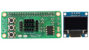
ANAVI Info uHAT is an affordable, open-source Raspberry Pi add-on board that brings extra functionality in a compact form. It features a mini OLED display, three buttons, red and green indicator LEDs, and slots for various sensors. Each kit includes a 0.96″ yellow-blue I²C OLED display with a resolution of 128×64 pixels.
At the start of 2025, Leon Anavi launched a series of video tutorials on the Yocto Project and OpenEmbedded. The Yocto Project, a collaborative initiative under the Linux Foundation, has become the de facto industry standard for creating custom Linux distributions tailored for embedded devices.
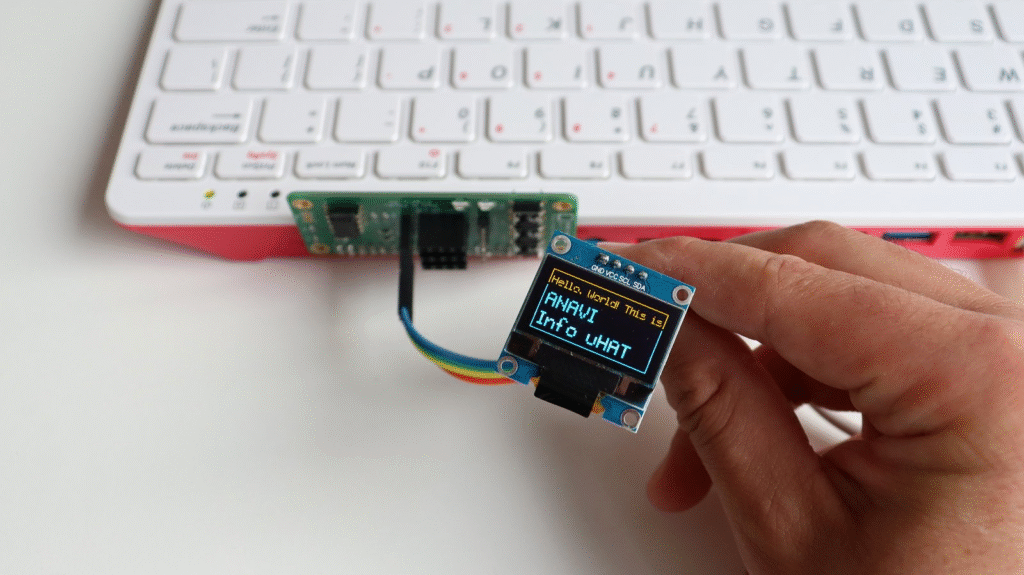
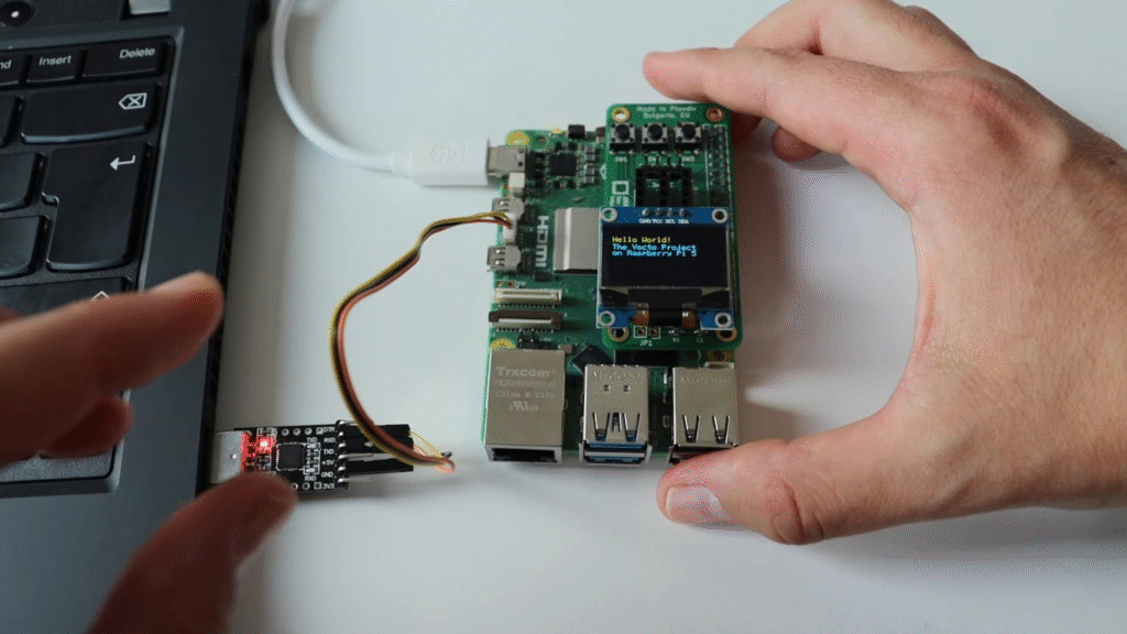
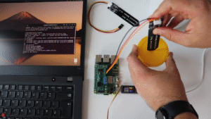
In Episode 9 from September 2025, Leon demonstrates how to enable I²C on a Raspberry Pi and use it with an SSD1306 mini OLED display. To simplify wiring, he used the ANAVI Info uHAT, attaching it directly to the Raspberry Pi 5’s 40-pin header, while the OLED display connected to its dedicated I²C port.
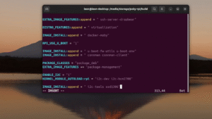
The demonstration from the video tutorial also included useful packages in the Yocto image to scan for I²C devices and interact with the SSD1306 OLED display:
IMAGE_INSTALL:append = " i2c-tools ssd1306"
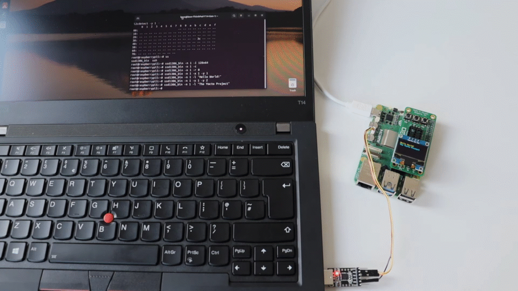
After building core-image-base and booting it on the Raspberry Pi, you can test the OLED using the open-source ssd1306_bin tool. Here are some sample commands from the tutorial:
This tutorial builds on concepts from previous episodes in the series, so if you are new to the Yocto Project on Raspberry Pi 5, it is highly recommended to start from the beginning. Watching the full video will give you a detailed walkthrough and context for each step.
In the world of electronics and IoT, gesture recognition has emerged as a fascinating and practical technology. Whether it’s controlling your favorite gadgets with the wave of a hand or adding a touch of magic to your projects, gesture recognition sensors play a pivotal role. Among the numerous sensors available, the APDS9960 stands out as a versatile and widely used I2C sensor at a very affordable price. In this blog post, we will take you on a journey through the fascinating world of gesture recognition using the APDS9960 sensor on a Raspberry Pi and any of our popular add-on boards: ANAVI Infrared pHAT, ANAVI Light pHAT, ANAVI Gardening uHAT, ANAVI Info uHAT as well as ANAVI Miracle uHAT and ANAVI CO2 uHAT (both of which are in final development).
What is APDS9960?
APDS9960 is an I2C (Inter-Integrated Circuit) sensor produced by Broadcom (formerly Avago Technologies). It is known for its versatility and is commonly used for gesture recognition, proximity sensing, ambient light sensing, and color sensing applications. Gestures are detected at a distance of 10 to 20 cm. The sensor has built-in UV and IR filters for better recognition. Its wide range of applications makes it a favorite choice among electronics enthusiasts, engineers, and hobbyists. Ovewr the years APDS9960 has been integrated in many popular consumer electronic devices, including Samsung Galaxy S5 smartphone.
In this tutorial, we will explore how to set up gesture detection on a Raspberry Pi running the Raspberry Pi OS Linux distribution. Specifically, we will use the APDS9960 I2C sensor connected to a Raspberry Pi uHAT (add-on board) and a mini OLED SSD1306 I2C yellow-blue display.
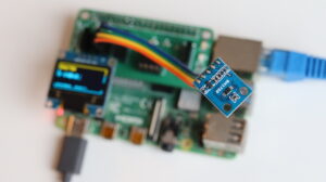
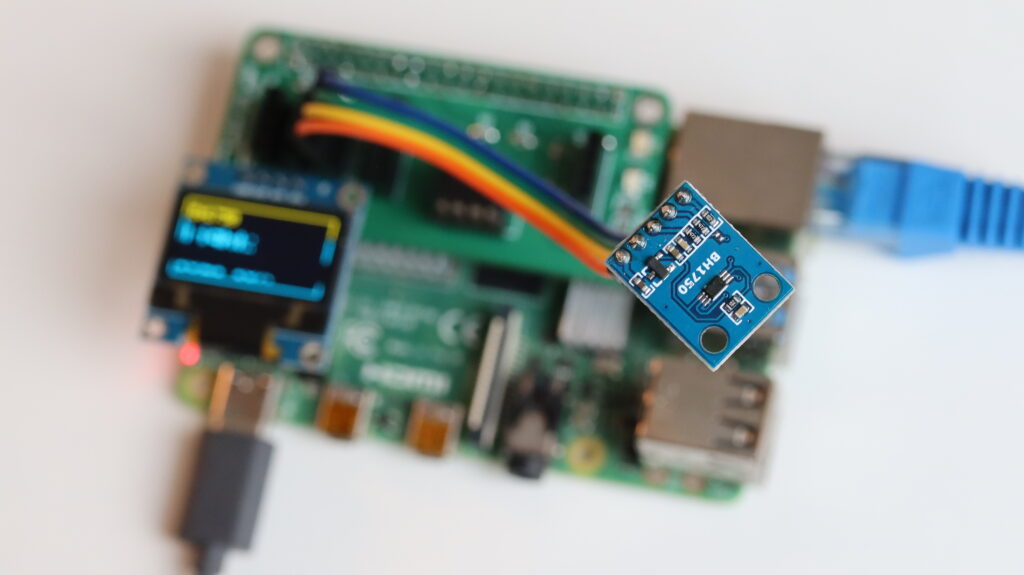
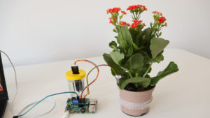
BH1750 I2C light sensor attached to ANAVI CO2 uHAT and a Raspberry Pi single board computer running GNU Linux distribution
🔌 Hardware Setup
Both APDS9960 sensor and the mini yellow-blue SSD1306 OLED display rely on the serial communication protocol I2C that allows multiple electronic devices to communicate with each other using only two wires: serial data (SDA) and serial clock (SCL). Raspberry Pi single board computers have two different I2C busses. The primary I2C bus is at GPIO 2 (physical pin 3 for SDA) and GPIO3 (physical pin 6 for SCL). These pins should be used to attach APDS9960 and the mini OLED display to the Raspberry Pi. Also APDS9960 should be connected to 3.3V and GND pins of the Raspberry Pi to be powered. This makes 4 wires in total to attach the sensor. ANAVI HATs (Hardware Attached on Top) for Raspberry Pi offer dedicated slots for I2C sensors. On ANAVI Info uHAT and ANAVI CO2 uHAT there are even dedicated slots for the mini OLED display.
Of course the OLED display is optional and as an alternative we offer a simple command-line Python3 example for APDS9960 which can function without the OLED display.
🖥️ Software Setup
The software setup is straight forward: install Raspberry Pi OS on microSD card, boot your Raspberry Pi and enable I2C using raspi-config. More details are available in the user’s manual for our HATs.
🐍 Python3 Scripts
The heart of our demonstration are scripts written in the Python 3 programming language. We’ve tailored the script to work seamlessly with Raspberry Pi OS, but it should also run smoothly on any other GNU Linux distribution. These scripts rely on popular Python3 libraries like PIL and Luma OLED. You can find the source code on GitHub for reference and further experimentation: https://github.com/AnaviTechnology/anavi-examples/tree/master/sensors/APDS-9960/python
There are two different Python 3 scripts to demonstrate APDS9960 gesture detection:
gesture-oled.py for detecting gestures and showing them on the mini OLED display as in the video
gesture.py for detecting gesture and printing them in the command-line interface (use this one if don’t have a suitable mini OLED display)
👁️ Real-Time Gesture Detection
Experience the magic as the APDS9960 sensor detects your hand movements, including swipes, taps, and more. Witness how your Raspberry Pi interprets and responds to these gestures in real-time, opening up a world of interactive possibilities. The video provides insights into potential issues you might face during setup and offers practical tips to ensure a seamless experience.
So, if you are ready to embark on this exciting journey into gesture recognition technology, grab your Raspberry Pi, APDS9960 sensor, and let’s get started!
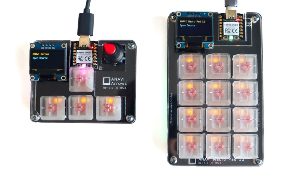
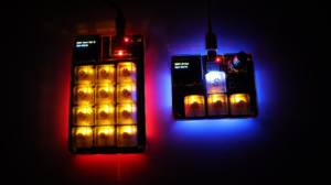
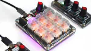
I2C (Inter-Integrated Circuit) is a popular serial communication protocol that allows multiple integrated circuits to communicate with each other over a short distance, typically limited to a few meters. Each device on the bus has a unique address, identifying it and allowing it to communicate individually. The protocol was developed by Philips (now NXP Semiconductors) in the 1980s. Over the years it has become a standard for communication between various electronic components in embedded devices. I2C can be used to connect various peripherals, such as sensors, displays and EEPROMs. The mini OLED yellw-blue displays on our compact mechanical keyboards ANAVI Macro Pad 12 and ANAVI Arrows are connected to the Raspberry Pi RP2040 microcontrollers over I2C.
ANAVI Arrows and ANAVI Macro Pad 12 are open source mechanical keyboards with mini OLED I2C displays
I2C is easy to use becase it requires only two wires for communication:
SDA (Serial Data) for transmitting and receiving data between devices
SCL (Serial Clock) for a clock signal to synchronizes the data transfer between the devices
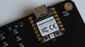
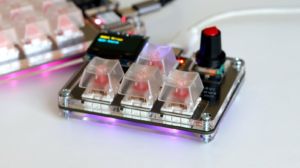
The core component of our hot-swappable mechanical keyboards ANAVI Macro Pad 12 and ANAVI Arrows is Seeed Studio XIAO RP2040 module. This is actually a tiny development board suitable for surface-mount technology (SMT) assembly and equipped with a Raspberry Pi RP2040 32-bit dual-core ARM Cortex M0+ MCU, 264 KB SRAM, 2 MB Flash memory, 11 GPIO pins and USB-C connector. The I2C interface is located on pins D4 (for SDA) and D5 (for SCL) of XIAO RP2040.
Seeed Studio XIAO RP2040 module on ANAVI Macro Pad 12 mechanical keyboard
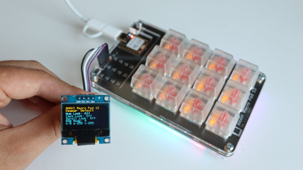
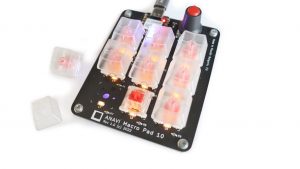
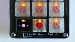
A yellow-blue mini OLED I2C display is included in all kits with ANAVI Macro Pad 12 and ANAVI Arrows. It has 4 pins: GND (ground), VCC (supply voltage), SCL, and SDA. This display relies on SSD1306, a single-chip CMOS OLED/PLED driver with controller for organic / polymer light emitting diode dot-matrix graphic display system which consists of 128 segments and 64 commons. It is the same display we include in our other mechanical keyboards like the ANAVI Macro Pad 10 and ANAVI Macro Pad 8, Internet of Things devices like the ANAVI Thermometer and ANAVI Gas Detector, tools like ANAVI Fume Extractor, and Raspberry Pi add-on boards like ANAVI Info uHAT. This versatile mini OLED display is a great fit for many projects, You can pick one up at Mouser if you need a spare.
Mini yellow-blue 0.96″ OLED display attached to ANAVI Macro Pad 12 with QMK firmware for mechanical keyboards
There is a dedicated slot for the display on the printed circuit board. Just plug the mini OLED display into it and then connect the mechanical keyboard to a computer. In every kit with ANAVI Macro Pad 12 and ANAVI Arrows, you will find four additional male-to-female jumper wires included, providing you with an exciting opportunity to get creative with your project. If you decide to design your own 3D printed case for the keyboard, these jumper wires may become handy. They grant you the flexibility to reposition the mini OLED display to a location of your choice within the case.
ANAVI Macro Pad 12 is compatible the two most popular open source firmwares for mechanical keyboards: KMK and QMK. KMK is written in CircuitPython and QMK in the C programming language. Both support OLED displays over I2C.
Out of the box ANAVI Macro Pad 12 and ANAVI Arrows come with the KMK firmware. It uses the extension Peg Oled Display based on the open source CircuitPython libraries Adafruit_CircuitPython_DisplayIO_SSD1306 and Adafruit_CircuitPython_Display_Text. This extension allows your keyboard to display images or text and even to react to the currently selected keyboard layer.
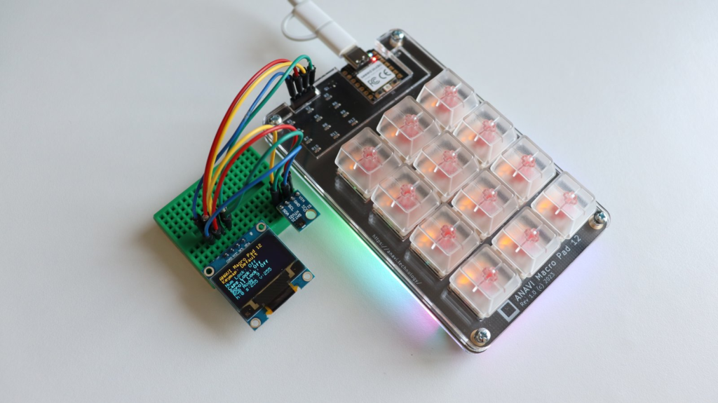
ANAVI Macro Pad 12 with a breadboard and additional I2C peripherals
Makers with advanced skills have a fantastic opportunity to extend the capabilities of the keyboard project by adding more I2C peripherals. Using a breadboard and without any soldering, makers can easily connect additional I2C peripherals, such as sensors or other modules that communicate via I2C, to the existing setup. This allows them to expand the project’s functionalities and explore various creative ideas. Those seeking a more permanent and tailored extension can even design their own custom I2C add-on printed circuit board. The mini OLED displays included in the kits work out of the box, but it is important to be aware that incorporating any other I2C devices into the keyboard will require adjusting the KMK firmware to support the additions.
Support our crowdfunding campaign and get the open source mechanical keyboards ANAVI Macro Pad 12 and ANAVI Arrows with a mini OLED display for real-time notifications and customizable graphics at your fingertips. Learn how to use I2C and unleash your creativity by extending the keyboard with additional peripherals!
I2C stands for Inter-Integrated Circuit, pronounced eye-squared-C, and alternatively known as IIC. It is a synchronous, multi-controller/multi-target (controller/target), packet switched, single-ended, serial communication bus. This protocol is suitable for devices wired at short distances, no more than 2-3m. We use I2C in pretty much all our open source products: Internet of Things, mechanical keyboards and Raspberry Pi HATs.
I2C sensor modules attached to ANAVI Info uHAT
I2C was originally developed in 1982 by Philips. While that makes it 40 years old, it is still a very convenient and widely used bus. There are many I2C sensors and peripherals. It is in pretty much every smartphone, embedded electronics, microcontroller, personal computer and of course Raspberry Pi.
ANAVI Info uHAT with 4 slots for I2C sensors and mini OLED dsiplay
Actually, since the introduction of the famous 40-pin header in 2014, Raspberry Pi single board computers have not one but two I2C buses! We use them both on ANAVI Info uHAT and our other HATs. Th first I2C bus is on pins 3 and 5. On the ANAVI Info uHAT, it is used for the three I2C slots for sensors and the 4th dedicated slot for the mini OLED display.
The I2C bus on ANAVI Info uHAT in KiCad’s Schematic Layout Editor.
The second I2C bus is on pins 27 and 28 of the Raspberry Pi and is reserved exclusively for attaching an ID EEPROM. The ID EEPROM contains a software description of the hardware so the operating system on your Raspberry Pi can automatically identify the add-on board.
The EEPROM on ANAVI Info uHAT attached on the 2nd I2C bus
The I2C bus consists of two signals: SDA (Serial Data) is a data signal, SCL (Serial Clock) is a clock signal. I2C modules also need power, so the dedicated I2C connectors on the ANAVI Info uHAT and our other open source hardware provide two additional pins for VCC and GND. Typically, the VCC for the I2C connectors on our add-on boards for Raspberry Pi are 3.3V.
The I2C bus drivers are “open drain”, which means they can only pull the corresponding signal line at low level. They cannot drive it high. To restore the signal to high when no device is asserting it low, a pull-up resistor has to be added to each signal line. For example, on the ANAVI Info uHAT, we have 4.7K pull-up resistors R4 and R5 connected to SDA and SCL.
Resistor selection varies depending on the devices attached to the bus. In some specific use cases, further adjustment of the resistance value might be required. For systems with lots of devices or longer wires, smaller resistors are better.
How to Enable I2C on Raspberry Pi OS
Raspberry Pi OS, previously known as Raspbian, is the default and recommended Linux distribution for all models and versions of the Raspberry Pi single board computer. By default, I2C is not enabled. There are several ways to enable it, but probably the easiest is using the command-line tool raspi-config to perform few basic commands:
Open a terminal or login remotely via SSH to your Raspberry Pi and type in the following command: sudo raspi-config
Each I2C device must have a unique address. The I2C reference design has a 7-bit address space, although rarely it might be used with a 10-bit extension. The 7-bit addresses range from 0 to 127 (0 to 0x7F hexadecimal). This is a limitation because it is not possible to have two I2C devices with the same address on the same I2C bus. For example, the I2C address on the mini OLED display included in all ANAVI Info uHAT kits is 0x3C. From the software side, this address is used in the example Python 3 script to access the display.
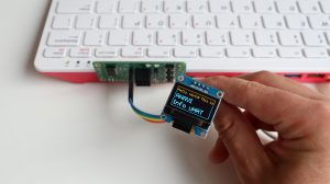
Python3 script controlling the mini OLED display over I2C on ANAVI Info uHAT
For Linux distributions, including Raspberry Pi OS, there is a package with a heterogeneous set of I2C tools called i2c-tools. To install it on Raspberry Pi OS, open a terminal and execute: sudo apt install -y i2c-tools. Once you have it installed, you can list attached I2C devices by their addresses with i2cdetect. For example, if the HTU21 temperature and humidity sensor module is attached to the Raspberry Pi, the output will be:
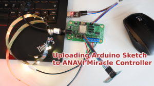
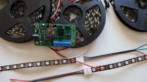
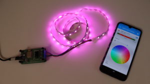
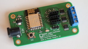
ANAVI Miracle Controller is an open source hardware Wi-Fi development board powered by the ESP8266 and designed to control two 5 V or 12 V addressable LED strips simultaneously.
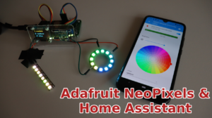
ANAVI Miracle Controller supports popular addressable LEDs including Neopixel, WS2811, WS2812B, TM1809, etc. It also has a dedicated slot for a mini OLED I²C display and slots for up to three additional I²C sensor modules. The default firmware is available at GitHub as an Arduino sketch implementing Home Assistant MQTT Light component.
Back in 2018 we created ANAVI Light Controller for low-cost 12V RGB LED strips. Inspired by a lot of people asking for open source hardware dev board for addressable LEDs strips we created ANAVI Miracle Controller.