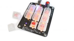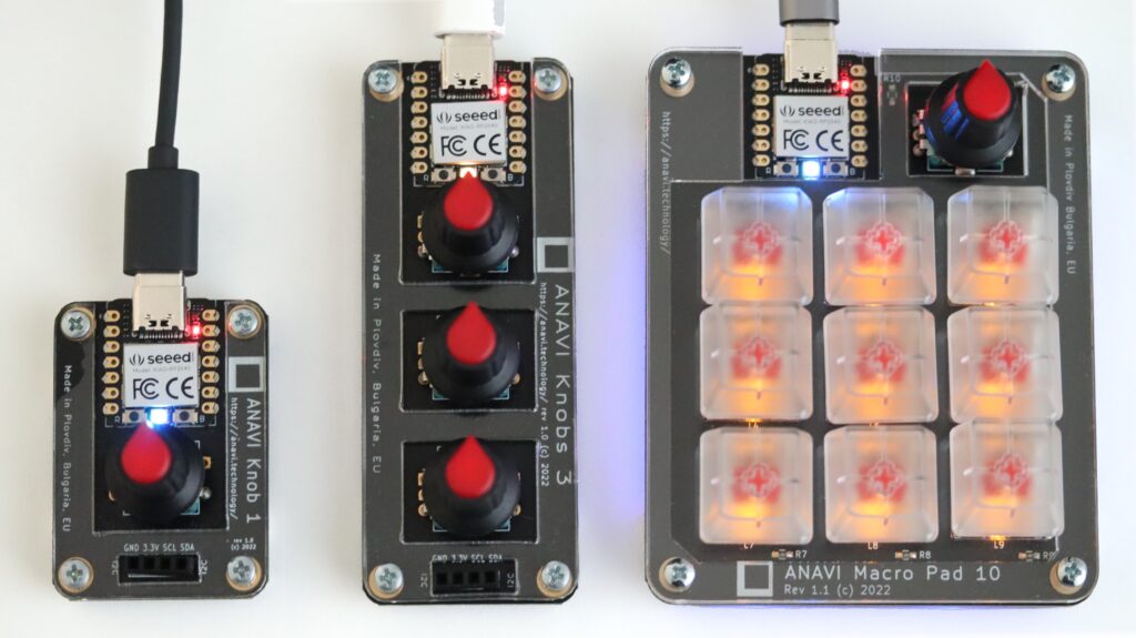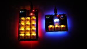
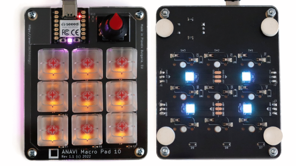
ANAVI Macro Pad 10 is our programmable keypad with 9 mechanical switches and a rotary encoder built around XIAO module with Raspberry Pi RP2040 microcontroller. ANAVI Macro Pad 10 was crowdfunded through Crowd Supply on November 7, 2022 and it is now available at Crowd Supply, Mouser and Lectronz. It illustrates how open hardware can act as a reusable foundation rather than a fixed product. Released under the permissive license Creative Commons Attribution-ShareAlike 4.0 International (CC BY-SA 4.0), ANAVI Macro Pad 10 allows others to study, modify, and fork the design while keeping attribution and share-alike requirements intact. That structure makes it easy for developers to adapt the device for different workflows without starting from scratch.
A recent fork is the MATOSIC MACROPAD, created by Hrvoje Matosic in Mexico City. It reworks the original design of ANAVI Macro Pad 10 into a compact macropad aimed at developers using AI-assisted coding tools. What makes this case interesting is not just the fork itself, but how naturally it extends the original design’s intent. The ANAVI Macro Pad 10 was never locked to a single use case, which makes it flexible enough to evolve into tools for new computing trends like AI-driven development workflows. This kind of reuse is exactly what open hardware licensing is meant to enable.
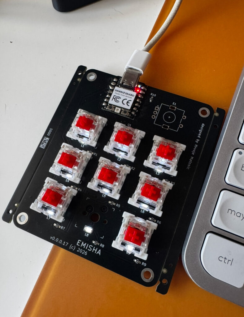
The project has also been certified by the Open Source Hardware Association with UID MX000040 on June 05, 2026, marking it as an officially recognized open hardware derivative from Mexico.
ANAVI Macro Pad 10 was also certified by the Open Source Hardware Association with UID BG000093 on January 11, 2023. Hrvoje shared his fork on GitHub. In this context, each derivative project strengthens the original ecosystem. The MATOSIC version does not replace the ANAVI design, it builds on it, showing how small, well-documented devices can become platforms for experimentation and productization.
Overall, the ANAVI Macro Pad 10 demonstrates how open source hardware grows through iteration. Its value is not only in what it is, but in what others can turn it into, from hobby builds to even certified commercial products!