As part of the covered stretch goals, each kit will include stickers from ANAVI Technology and KiCad, the free and open source CAD software used for designing the printed circuit boards of the keyboards. Furthermore, ANAVI Macro Pad 10 kits will include 32 super-cool emoji stickers. You can stick them on the top or sides of the translucent keycaps. Last but not least, we’ll be publishing various video tutorials to ensure getting started is easy.
One more thing… Recently, our mini mechanical keyboards were featured in an article by CNX Software. This is a very popular website with news and tutorials about embedded systems, makers, and open source hardware. It was started in 2010 by Jean-Luc Aufranc. By the way it is worth keep an eye on CNX Software because there are always news about interesting gadgets!
I2C stands for Inter-Integrated Circuit, pronounced eye-squared-C, and alternatively known as IIC. It is a synchronous, multi-controller/multi-target (controller/target), packet switched, single-ended, serial communication bus. This protocol is suitable for devices wired at short distances, no more than 2-3m. We use I2C in pretty much all our open source products: Internet of Things, mechanical keyboards and Raspberry Pi HATs.
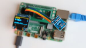
I2C sensor modules attached to ANAVI Info uHAT
I2C was originally developed in 1982 by Philips. While that makes it 40 years old, it is still a very convenient and widely used bus. There are many I2C sensors and peripherals. It is in pretty much every smartphone, embedded electronics, microcontroller, personal computer and of course Raspberry Pi.
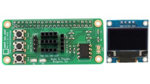
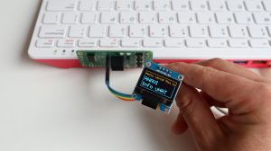
ANAVI Info uHAT with 4 slots for I2C sensors and mini OLED dsiplay
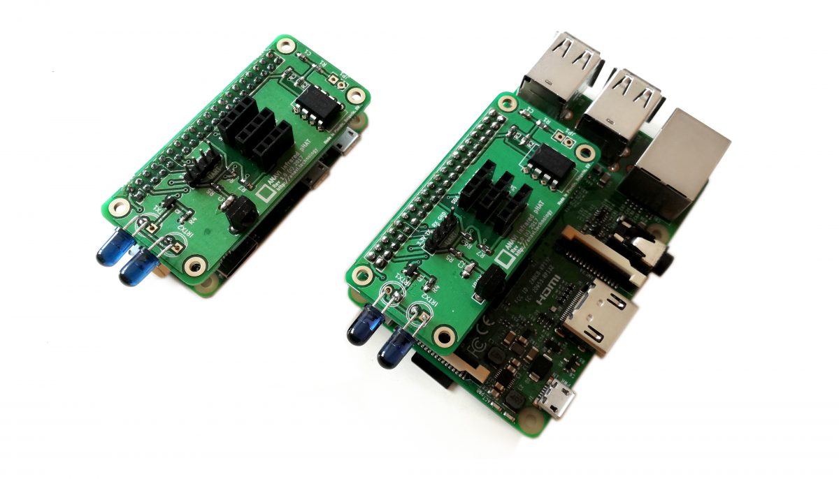
Actually, since the introduction of the famous 40-pin header in 2014, Raspberry Pi single board computers have not one but two I2C buses! We use them both on ANAVI Info uHAT and our other HATs. Th first I2C bus is on pins 3 and 5. On the ANAVI Info uHAT, it is used for the three I2C slots for sensors and the 4th dedicated slot for the mini OLED display.
The I2C bus on ANAVI Info uHAT in KiCad’s Schematic Layout Editor.
The second I2C bus is on pins 27 and 28 of the Raspberry Pi and is reserved exclusively for attaching an ID EEPROM. The ID EEPROM contains a software description of the hardware so the operating system on your Raspberry Pi can automatically identify the add-on board.
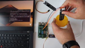
The EEPROM on ANAVI Info uHAT attached on the 2nd I2C bus
The I2C bus consists of two signals: SDA (Serial Data) is a data signal, SCL (Serial Clock) is a clock signal. I2C modules also need power, so the dedicated I2C connectors on the ANAVI Info uHAT and our other open source hardware provide two additional pins for VCC and GND. Typically, the VCC for the I2C connectors on our add-on boards for Raspberry Pi are 3.3V.
The I2C bus drivers are “open drain”, which means they can only pull the corresponding signal line at low level. They cannot drive it high. To restore the signal to high when no device is asserting it low, a pull-up resistor has to be added to each signal line. For example, on the ANAVI Info uHAT, we have 4.7K pull-up resistors R4 and R5 connected to SDA and SCL.
Resistor selection varies depending on the devices attached to the bus. In some specific use cases, further adjustment of the resistance value might be required. For systems with lots of devices or longer wires, smaller resistors are better.
How to Enable I2C on Raspberry Pi OS
Raspberry Pi OS, previously known as Raspbian, is the default and recommended Linux distribution for all models and versions of the Raspberry Pi single board computer. By default, I2C is not enabled. There are several ways to enable it, but probably the easiest is using the command-line tool raspi-config to perform few basic commands:
Open a terminal or login remotely via SSH to your Raspberry Pi and type in the following command: sudo raspi-config
Each I2C device must have a unique address. The I2C reference design has a 7-bit address space, although rarely it might be used with a 10-bit extension. The 7-bit addresses range from 0 to 127 (0 to 0x7F hexadecimal). This is a limitation because it is not possible to have two I2C devices with the same address on the same I2C bus. For example, the I2C address on the mini OLED display included in all ANAVI Info uHAT kits is 0x3C. From the software side, this address is used in the example Python 3 script to access the display.
Python3 script controlling the mini OLED display over I2C on ANAVI Info uHAT
For Linux distributions, including Raspberry Pi OS, there is a package with a heterogeneous set of I2C tools called i2c-tools. To install it on Raspberry Pi OS, open a terminal and execute: sudo apt install -y i2c-tools. Once you have it installed, you can list attached I2C devices by their addresses with i2cdetect. For example, if the HTU21 temperature and humidity sensor module is attached to the Raspberry Pi, the output will be:
OSHWA runs the certification program ensures that the definition of “open source hardware” used by a specific project matches the community’s definition of open source hardware. They provide a unique indentification (UID) for each version of the certified hardware based on the country code and a serial number. For example, the UID for ANAVI Info uHAT is BG000081. The prefix BG is the country code for Bulgaria, because the Info uHAT is made in my hometown of Plovdiv. The serial numbers show that now there are 81 open source hardware devices from Bulgaria.
How to build an air quality monitor using Raspberry Pi Zero W + ANAVI Infrared pHAT
MH-Z19B is an intelligent infrared CO2 module which interacts with the Raspberry Pi using UART (universal asynchronous receiver-transmitter). Takuya uses the UART port on ANAVI Infrared pHAT to attach MH-Z19B. The rest of the sensor modules for his setup are included in ANAVI Infrared pHAT Advanced kit: HTU21D for temperature and humidity, BMP180 for barometric pressure and BH1750 for light.
By the way, initially we had published open source examples for using HTU21D, BMP180 and BH1750 in the C programming languages using the library wiringpi. Takuya also based his setup on wiringpi. However, wiringpi is now deprecated therefore we have replaced it with another library called libi2c-dev. Furthermore we added examples written in Python 3.
We have good news regarding ANAVI Gardening uHAT! All boards have been received almost fully assembled from the local factory and we have sourced all required peripherals.
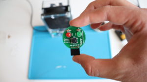
Recently, we received the last batch of assembled printed circuit boards from the local factory. As you can see on the photo, only the EEPROM is missing. We will flash and solder it in-house.
The winter is coming… Grab a ANAVI Gardening uHAT for your Raspberry Pi
We have also received additional peripherals, which will be included in ANAVI Gardening uHAT Starter, Advanced, and Developer kits. On the photo you can see the big packages with analog capacitive soil moisture sensor. Each kit will contain a couple of capacitive soil moisture sensors.
Capacitive Soil Moisture Sensor v1.2
The recyclable cardboard boxes for our eco-friendly packaging have also already been delivered. Another local company here in Plovdiv, Bulgaria will print all stickers for us. We expect them next week.
Our crowdfunding campaign recently ended very successfully but you can still order our open source Gardening uHAT for your Raspberry Pi and be among the very first owners!
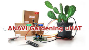
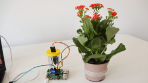
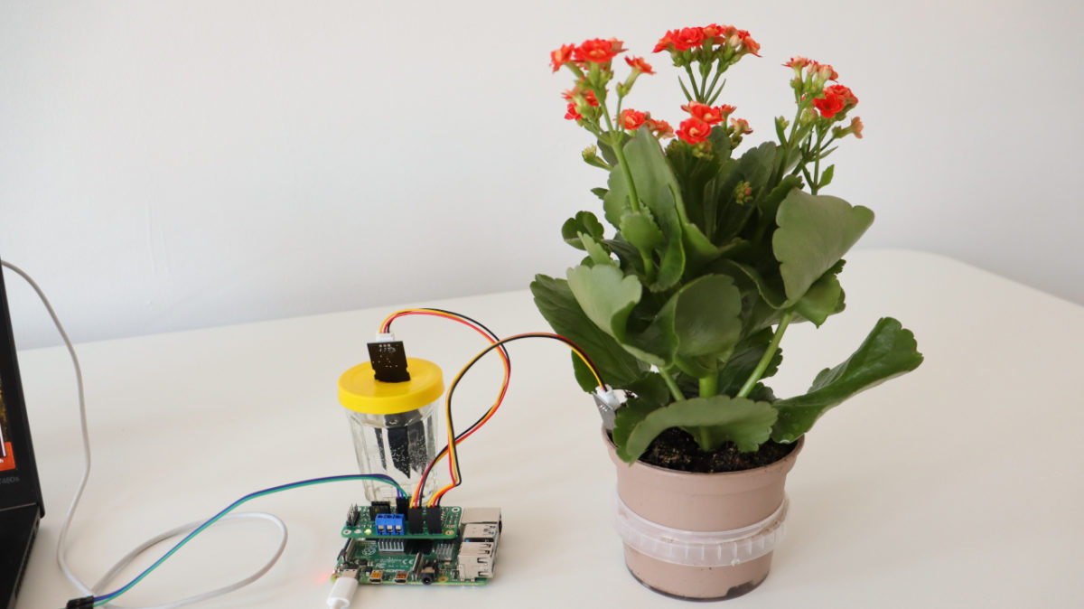
ANAVI Gardening uHAT is a low-cost, open source Raspberry Pi add-on board that helps you develop smart solutions for monitoring and growing plants.
ANAVI Gardening uHAT supports multiple sensors for soil moisture, temperature, humidity, barometric pressure, and light. Getting started is easy: just plug it into a Raspberry Pi with your bare hands and follow the instructions in the user manual. No soldering is necessary, and no tools are required.
Raspberry Pi is a famous series of small single-board computers (SBCs) developed in the United Kingdom by the Raspberry Pi Foundation in cooperation with Broadcom. This is a step by step tutorial for using Raspberry Pi and capacitive soil moisture sensor with Microchip MCP3002 analog-to-digital converter (ADC) and a Python script for detecting the soil moisture in percentage.
Capacitive Soil Moisture Sensor
Capacitive Soil Moisture Sensor v1.2 and v2.0 measures the volumetric content of water inside the soil and retrieves the moisture level by capacitive sensing rather than resistive sensing like other sensors. The benefit of using a capacitive soil moisture sensor is the lack of corrosion and longer lifespan.
Wiring
Unlike Raspberry Pi Pico, the recently released microcontroller, all versions and models of the Raspberry Pi single-board computers do not include an analog-to-digital converter (ADC). This tutorial explains how to use Microchip MCP3002 with Raspberry Pi.
Microchip MCP3002 is a 10-bit resolution, dual channel ADC with SPI hardware bus. It can be connected to any Raspberry Pi single board computer version and model, including Raspberry Pi 4 and Raspberry Pi 0. However, this tutorial is not for Raspberry Pi Pico microcontroller. For more details about the wiring of Microchip MCP3002 a Raspberry Pi single-board computer have a look at my previous tutorial.
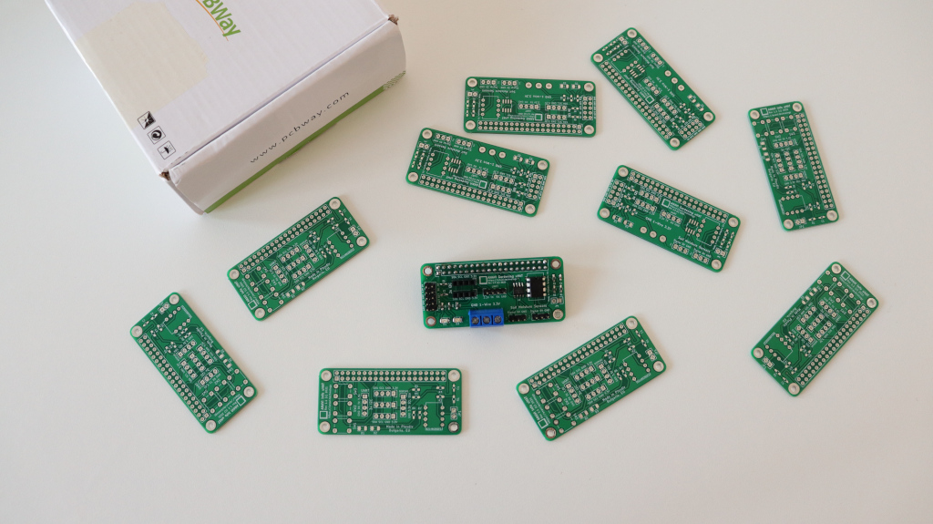
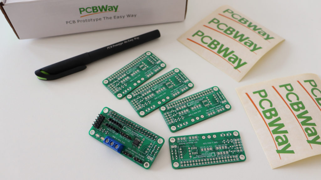
Prototypes for Raspberry Pi add-on boards
Alternatively, the easier option without a breadboard an a bunch of cables, is to use a dedicated Raspberry Pi add-on board with built-in ADC. Using the free and open source tool KiCad we designed ANAVI Gardening uHAT exactly for this purpose. It has dedicated pins for connecting a couple of capacitive soil moisture sensors. The prototype has been created thanks to PCBWay. This is a lead-free prototype printed circuit board with 2 layers, green solder mask and white silkscreen. PCBway offers a huge variety of colors and even flexible PCB.
Software
Flash Raspberry Pi OS, the official Debian based GNU Linux distribution by the Raspberry Pi, on microSD card and boot it. On the Raspberry Pi, open a terminal and using the raspi-config tool enable SPI as shown in the video. Reboot the Raspberry Pi.
Python3 script for reading data from a couple of capacitive soil moisture sensors through Microchip MCP3002 ADC is available at the anavi-examples repository in GitHub. The script relies on popular Python libraries spidev and RPi.GPIO. Open a terminal and run the following commands to clone anavi-examples and run the script:
git clone https://github.com/AnaviTechnology/anavi-examples.git
cd anavi-examples/anavi-gardening-uhat/soil-moistore-sensors/python/
python3 soil-moistore-sensors.py
If you are reading this blog post, I am sure you are familiar with Raspberry Pi, the a series of small single-board computers (SBCs) developed in the United Kingdom by the Raspberry Pi Foundation in cooperation with Broadcom. Unlike the recently released microcontroller Raspberry Pi Pico, all versions and models of the Raspberry Pi Linux computers do not include an analog-to-digital converter (ADC). If you need to read data from an analog device such as a potentiometer, sound or soil moisture sensor the solution is to use an external ADC, for example Microchip MCP3002.
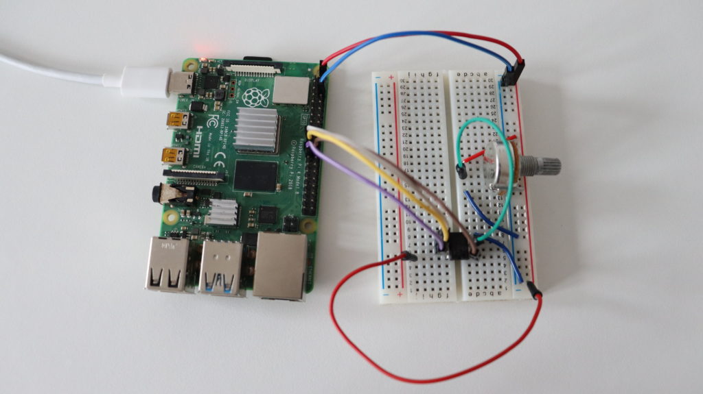
Prototyping on a breadboard with Raspberry Pi 4, 10K potentiometer and Microchip MCP3002 ADC
Microchip MCP3002 ADC
Microchip MCP3002 is a 10-bit resolution dual channel ADC with SPI hardware interface for connecting to embedded devices such as Raspberry Pi. MCP3002 operates over a broad voltage range, from 2.7V to 5.5V. It is offered in 8-pin MSOP, PDIP, TSSOP and 150 mil SOIC packages. MCP3002 PDIP package is appropriate for prototyping on a breadboard.
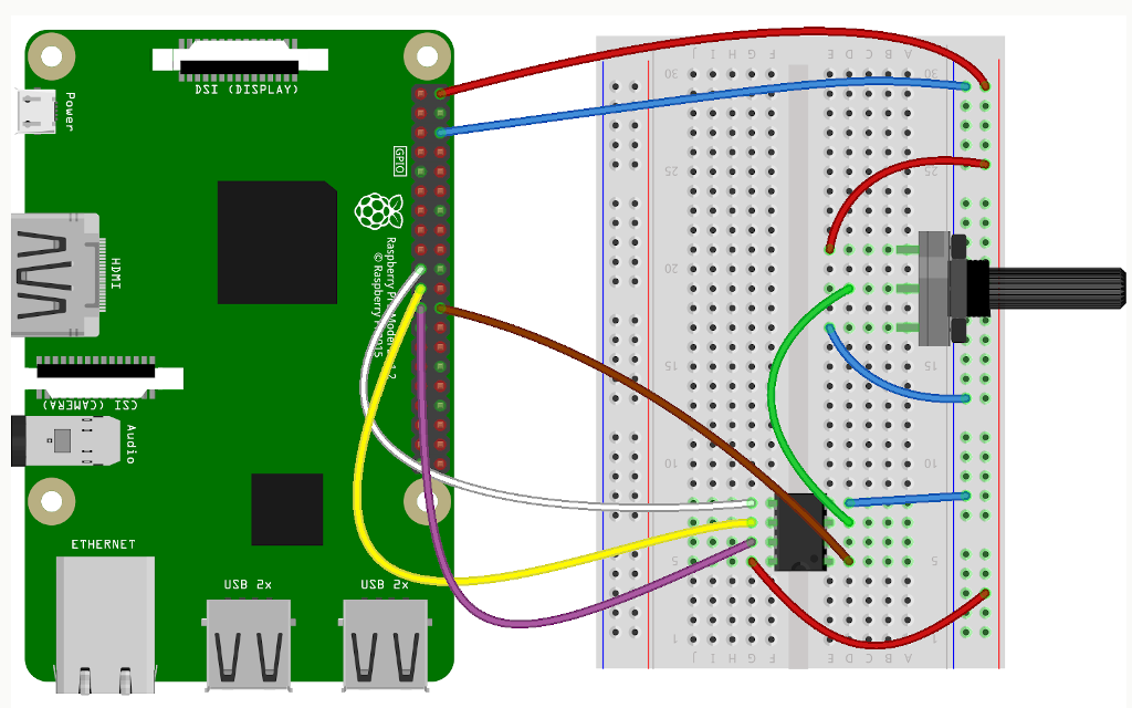
Raspberry Pi and Microchip MCP3002 Wiring
Microchip MCP3002 has to be connected to the dedicated SPI pins (MISO, MOSI, SCL and SS) on the Raspberry Pi GPIO header. In the video a 10K potentiometer is connected to one of the two channels of the ADC for testing purposes. The potentiometer as well as Microchip MCP3002 are powered with 5V from the Raspberry Pi.
Microchip MCP3002 attached to Raspberry Pi 4 over SPI
Enable SPI
Boot Raspberry Pi OS, the official Debian based GNU Linux distribution by the Raspberry Pi, from a microSD card. Open a terminal and using the raspi-config tool enable SPI as shown in the video. After that reboot the Raspberry Pi and proceed to the next step.
Reading Data with Python
Python3 script for reading data from analog devices through MCP3002 is available at the rpi-examples repository in GitHub. The script relies on popular Python package RPi.GPIO. Open a terminal and run the following commands to clone rpi-example and run the script:
git clone https://github.com/leon-anavi/rpi-examples.git
cd rpi-examples/MCP3002/python
python3 adc.py
The potentiometer acts like a variable resistor. Rotate it and observe the output of the Python script. You will notice a change of the voltage between 0V and 5V depending on the position of the potentiometer.
ANAVI Garderning uHAT
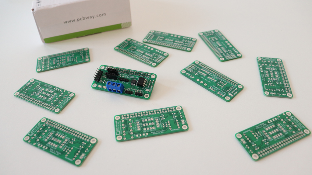
Thanks to PCBway, the sponsor of this video, we can go to the next level and use a prototype of ANAVI Gardening uHAT as a Raspberry Pi add-on board with SOIC package of Microchip MCP3002. ANAVI Gardening uHAT follows the specifications of Raspberry Pi Foundation for HAT (hardware attached on top), including for an EEPROM with device-tree binary overlay configurations.
Prototypes of the new Raspberry Pi add-on board with Microchip MCP3002 ADC from PCBWay
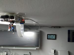
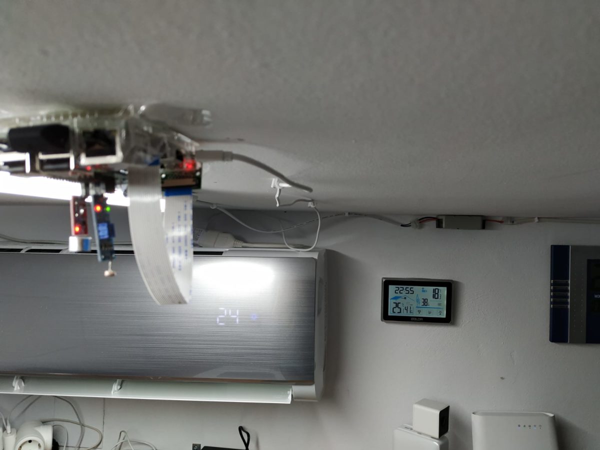
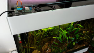
This is my RasPi called "spiderman", which is living upside down on my lab's ceiling collecting sensor data and taking pics to all those numbers. I hope its @leonanavi's infrared hat will transmit orders every 10m from my energy efficiency algorithms running in the cloud 😛 pic.twitter.com/90qk6P4ccC
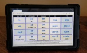
Jesús has attached various sensors for collecting data as we as a Raspberry Pi camera to take pictures of the room. He has developed energy efficiency algorithms running in the cloud which make decisions based on the data from the sensor and after that ANAVI Infrared pHAT takes care for transmitting commands as a stream of infrared signals to his air conditioner.
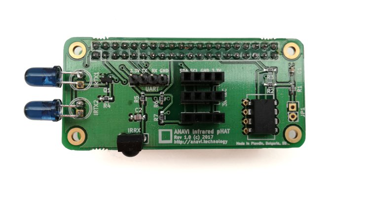
ANAVI Infrared pHAT
ANAVI Infrared pHAT is a low-cost open source hardware add-on board for Raspberry Pi with infrared receiver and transmitted. Furthermore it has slots for attaching up to 3 I2C sensor modules as well as convenient UART pins. We launched it in 2017 and it is one of our best-selling products. ANAVI Infrared pHAT is available at our distributors around the world and you can order it to build a similar home automation solution.