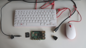

If you are reading this blog post, I am sure you are familiar with Raspberry Pi, the a series of small single-board computers (SBCs) developed in the United Kingdom by the Raspberry Pi Foundation in cooperation with Broadcom. Unlike the recently released microcontroller Raspberry Pi Pico, all versions and models of the Raspberry Pi Linux computers do not include an analog-to-digital converter (ADC). If you need to read data from an analog device such as a potentiometer, sound or soil moisture sensor the solution is to use an external ADC, for example Microchip MCP3002.
Microchip MCP3002 ADC
Microchip MCP3002 is a 10-bit resolution dual channel ADC with SPI hardware interface for connecting to embedded devices such as Raspberry Pi. MCP3002 operates over a broad voltage range, from 2.7V to 5.5V. It is offered in 8-pin MSOP, PDIP, TSSOP and 150 mil SOIC packages. MCP3002 PDIP package is appropriate for prototyping on a breadboard.
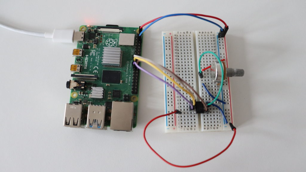
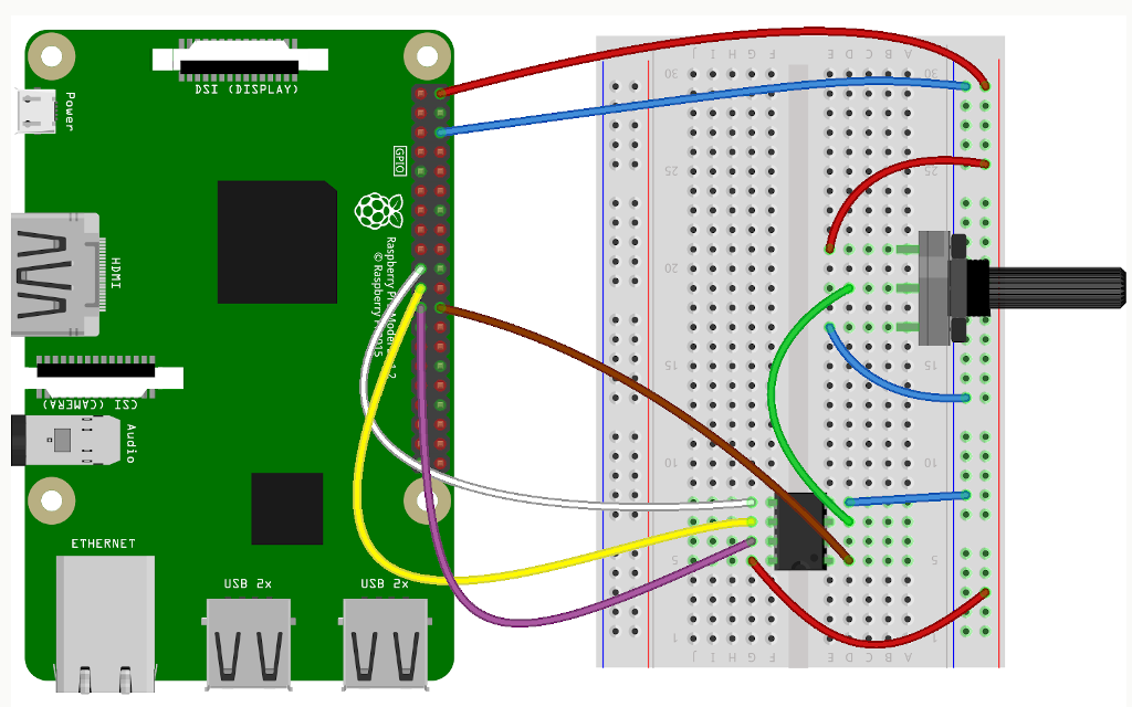
Raspberry Pi and Microchip MCP3002 Wiring
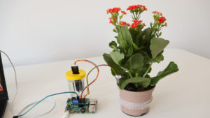
Microchip MCP3002 has to be connected to the dedicated SPI pins (MISO, MOSI, SCL and SS) on the Raspberry Pi GPIO header. In the video a 10K potentiometer is connected to one of the two channels of the ADC for testing purposes. The potentiometer as well as Microchip MCP3002 are powered with 5V from the Raspberry Pi.
Enable SPI
Boot Raspberry Pi OS, the official Debian based GNU Linux distribution by the Raspberry Pi, from a microSD card. Open a terminal and using the raspi-config tool enable SPI as shown in the video. After that reboot the Raspberry Pi and proceed to the next step.
Reading Data with Python
Python3 script for reading data from analog devices through MCP3002 is available at the rpi-examples repository in GitHub. The script relies on popular Python package RPi.GPIO. Open a terminal and run the following commands to clone rpi-example and run the script:
git clone https://github.com/leon-anavi/rpi-examples.git
cd rpi-examples/MCP3002/python
python3 adc.py
The potentiometer acts like a variable resistor. Rotate it and observe the output of the Python script. You will notice a change of the voltage between 0V and 5V depending on the position of the potentiometer.
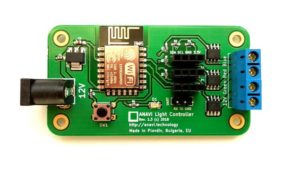
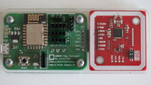
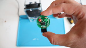
ANAVI Garderning uHAT
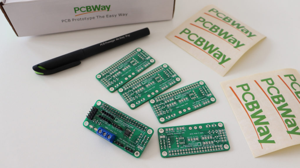
Thanks to PCBway, the sponsor of this video, we can go to the next level and use a prototype of ANAVI Gardening uHAT as a Raspberry Pi add-on board with SOIC package of Microchip MCP3002. ANAVI Gardening uHAT follows the specifications of Raspberry Pi Foundation for HAT (hardware attached on top), including for an EEPROM with device-tree binary overlay configurations.