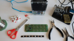
Please have a look at the video and follow the steps below to assemble ANAVI Macro Pad 8 Developer kit. Although you can do it with your bare hands, simple tools like a screwdriver, tweezers and a keycap puller might be useful.
ANAVI Macro Pad 8 developer kit comes with 8 Gateron mechanical switches and red leds. If you prefer another type of switches or color of the LEDs, please have a look at the Maker kit which requires soldering but allows to use different Cherry MX compatible switches or even make a hot-swap upgrade.
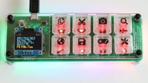
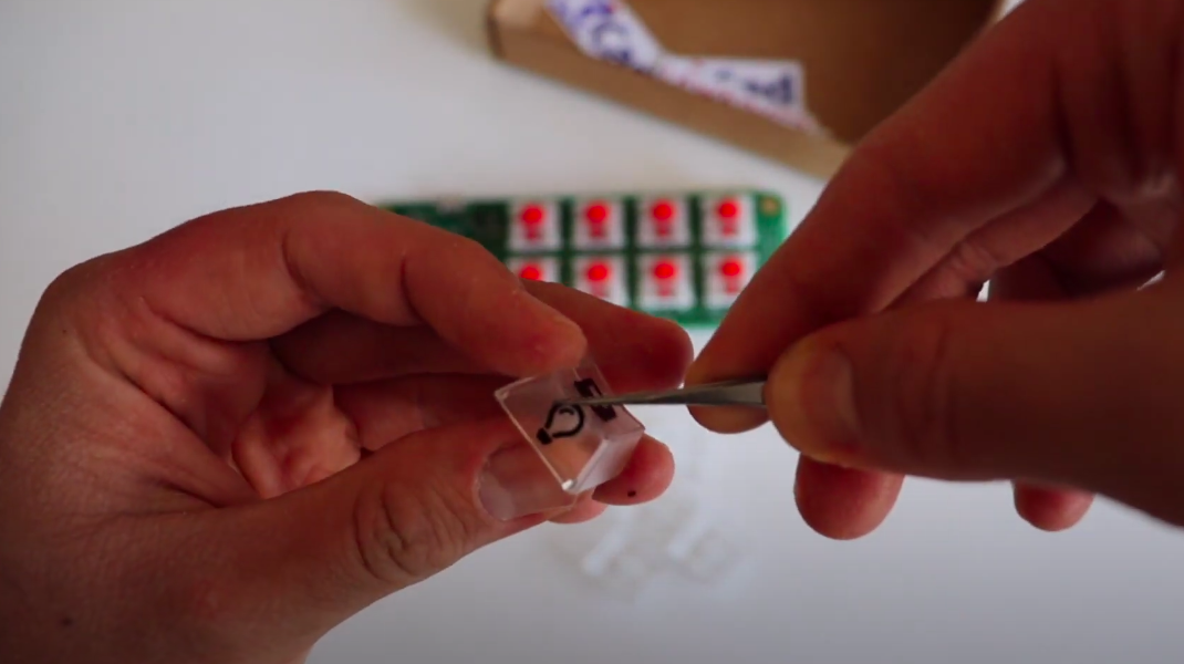
Step 1: Stickers
The first step optional. Each kit includes a set stickers. Feel free to add them to the translucent keycaps included in ANAVI Macro Pad 8 developer kit. You can do it with your bare hand or eventually with the help of tweezers.

You can place a sticker on the top or on the side of the keycap. If you like retro electronics you may find some similarities in this approach to the famous keyboard of the best selling personal computer of the 20th century Commodore 64.
ANAVI Macro Pad 8 is powered by the popular open source firmware QMK which allows you to create various layouts. You can make a keymap with 2 or more layouts. A sticker on the side of the keycap might be useful as a visual aid to indicate the additional function of the key.
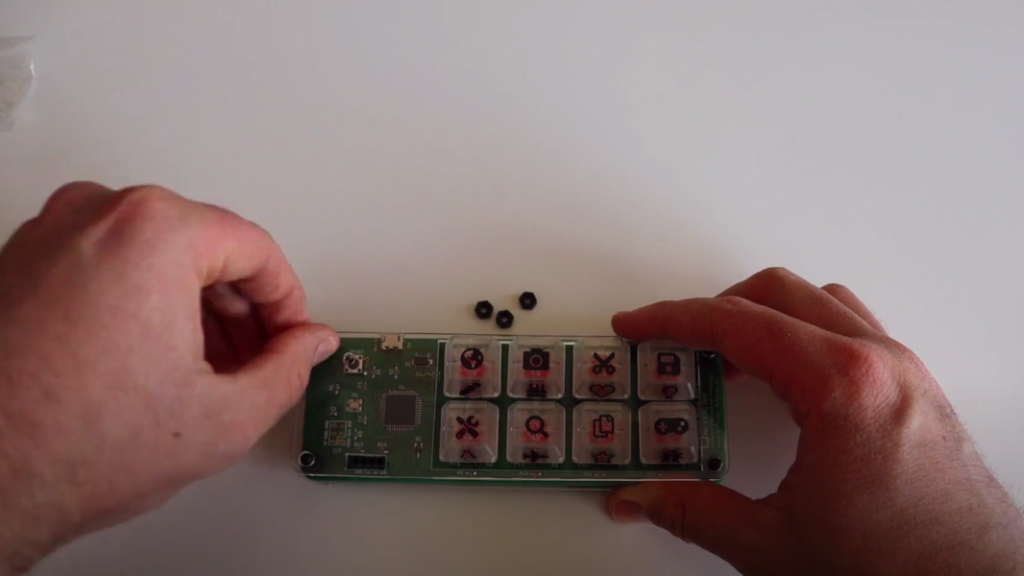
Step 2: Keycaps
Place all keycaps on 8 mechanical switches of ANAVI Macro Pad 8. You can easily do this with your bare hands. It takes just a few seconds.
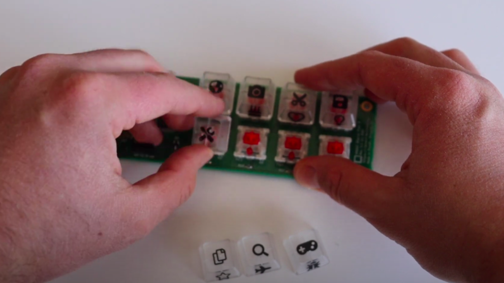
As you can see in the video a keycap puller might be useful if you make a mistake and want to pull off a keycap and place it on another location.
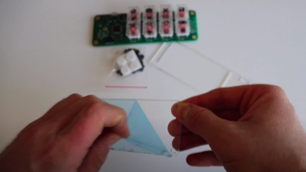
Step 3: Peel Off Protective Films from the Acrylic Enclosure
Peel off the protective films from both sides of the two laser cut transparent acrylic parts. The removal of the protective films is quite annoying but once you get rid of them, the acrylic enclosure will be crystal clear and fully transparent.
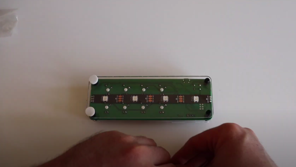
Step 4: Assemble the Acrylic Enclosure
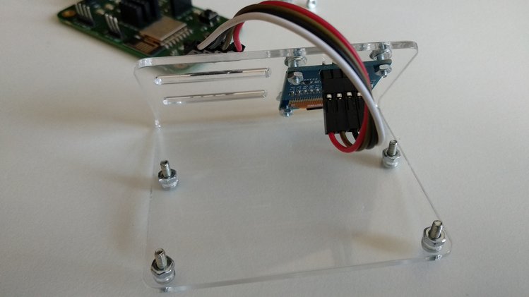
Assemble the acrylic enclosures. In the cardboard box you also will find M3 black plastic screws, nuts and standoffs. Although you can assemble them with your bare hands a screw driver might be handy.
First place 4 of stand-offs with screws to the bottom acrylic part. After that place ANAVI Macro Pad 8 on top of them. The printed circuit board has 4 mounting holes for this purpose.
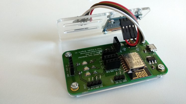
Add the rest of stand-offs on top of ANAVI Macro Pad 8 to secure the printed circuit board to the bottom part as shown in the video. Place the top acrylic part and fasten it with the 4 M3 nuts. Finally add the silicon protective pads on the screws on the bottom.
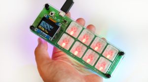
Step 5: Mini OLED Display
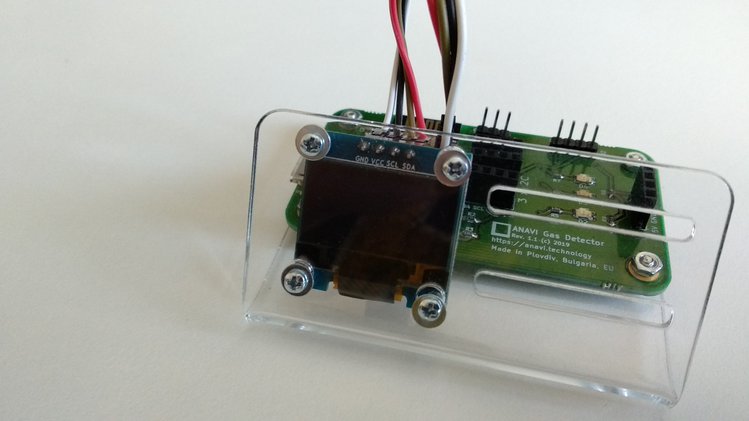
Step number 5 is optional. The default open source QMK firmware for ANAVI Macro Pad 8 support mini OLED display connected over the communication bus I2C.
By default mini display in yellow-blue 0.96″ I2C OLED. It comes with 4 jumper wires which might be useful for debugging purposes or if you plan to make a custom 3D printed case. However for the default acrylic enclosure the wires are not needed.
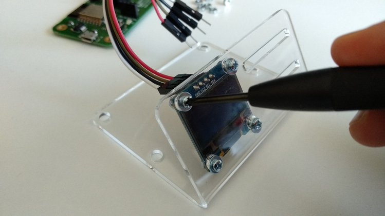
Peel off the protected film and place the mini OLED display as shown in the video to ANAVI Macro Pad 8. Pay attention to the labels that indicated the pin connectors of the display. They must match the labels on the keyboard.
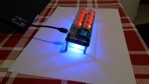
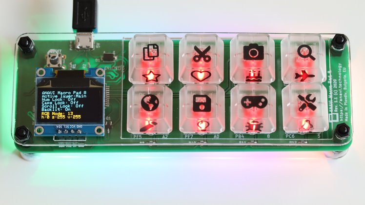
Step 6: Turn On ANAVI Macro Pad 8
Gently plug a USB to microUSB cable to connect ANAVI Macro Pad 8 to a personal computer. Please be careful with the microUSB connector because a harsh bending of the USB cable may damage the microUSB connector.
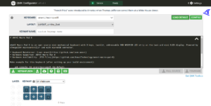
Thanks to the QMK firmware ANAVI Macro Pad 8 will be detected as human interface device and should work out of the box. Furthermore with QMK you have the freedom to fully customize each key.
Please note that a USB to microUSB cable is not included in any of the kits. Reuse a cable from an old electronic device or purchase a cable according to your taste. Make sure that the cable supports both power and data transfer over USB.
Thank you for supporting and using our open source kits. Stay tuned for more updates, including details for soldering ANAVI Macro Pad 8 Maker kit.