Flashing Firmware on ANAVI Miracle Controller with Arduino IDE

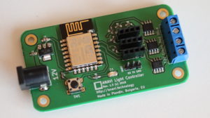
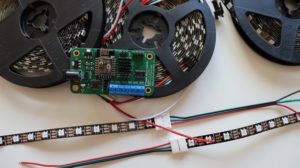
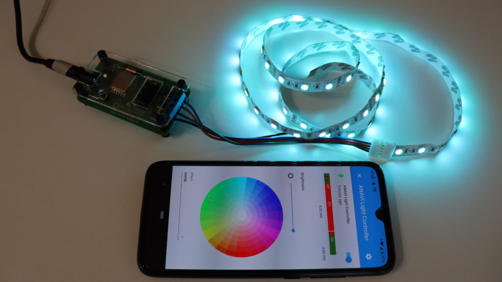
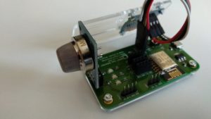
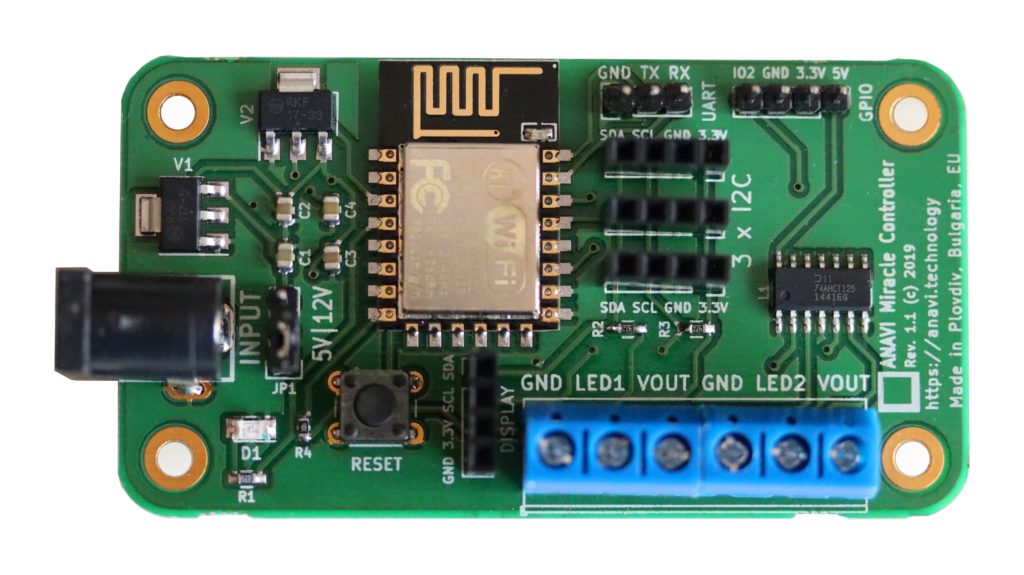
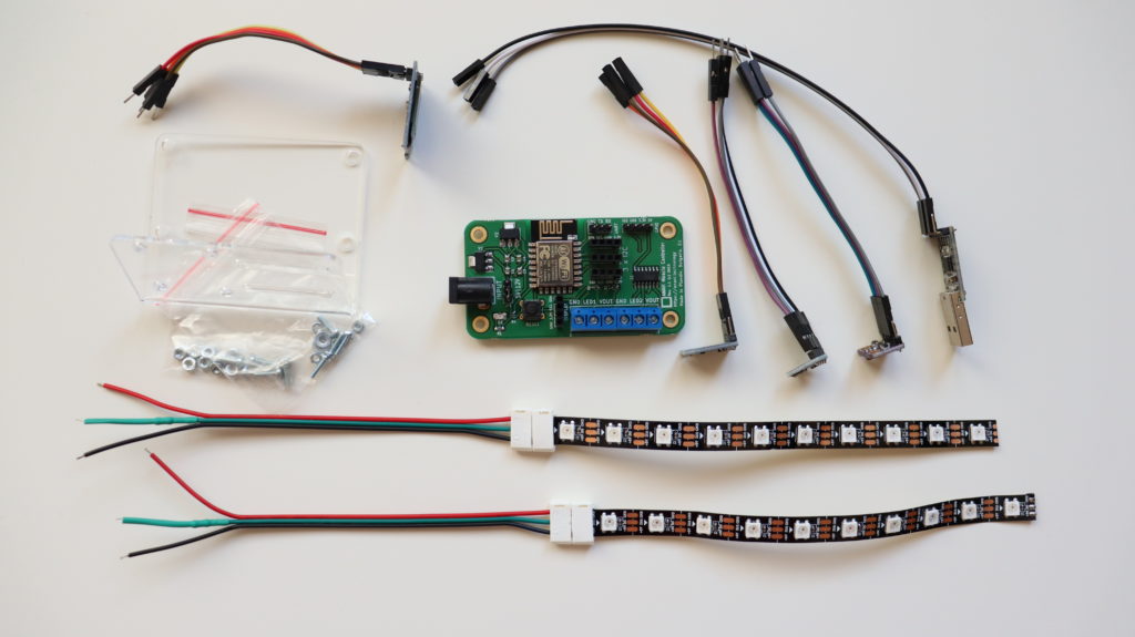
ANAVI Miracle Controller is a new entirely open source development board for addressable (digital) LED strips like NeoPixels, WS2812B, WS2811, etc. The major advantages are that you can control two LED strips simultaneously, add a mini OLED display and I2C sensor modules as peripherals. Recently we launched a crowdfunding campaign for it at Crowd Supply.

ANAVI Miracle Controller

ANAVI Miracle Controller is a development board and it is easy to flash a custom firmware on it. The process is very similar as for our other open source project like ANAVI Thermometer, ANAVI Gas Detector and ANAVI Light Controller.

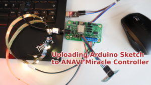
This tutorial explains the exact steps how to compile and upload the default open source Arduino sketch for ANAVI Miracle Controller using Arduino IDE.

Required Hardware

  • ANAVI Miracle Controller
  • USB to UART debug cable
  • Addressable LED strip
  • Appropriate power supply at 5V or 12V depending on the type of LED strips
  • Personal computer with MS Widows, Mac OS or GNU/Linux distribution
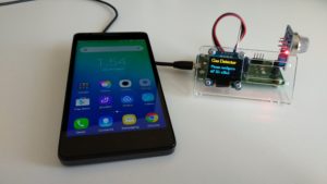
  • Optionally a mini OLED display and other peripherals can be attached
ANAVI Miracle Developer kit

Download Source Code from GitHub

The default firmware of ANAVI Miracle Controller is an open source Arduino sketch. It relies on several popular open source Arduino libraries, including FastLED for controlling addressable LED strips. Clone or download the source code from GitHub.

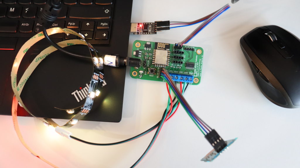
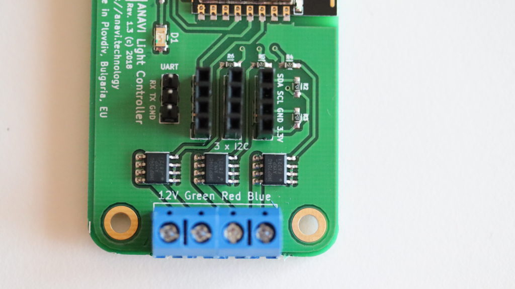
Connecting UART to USB

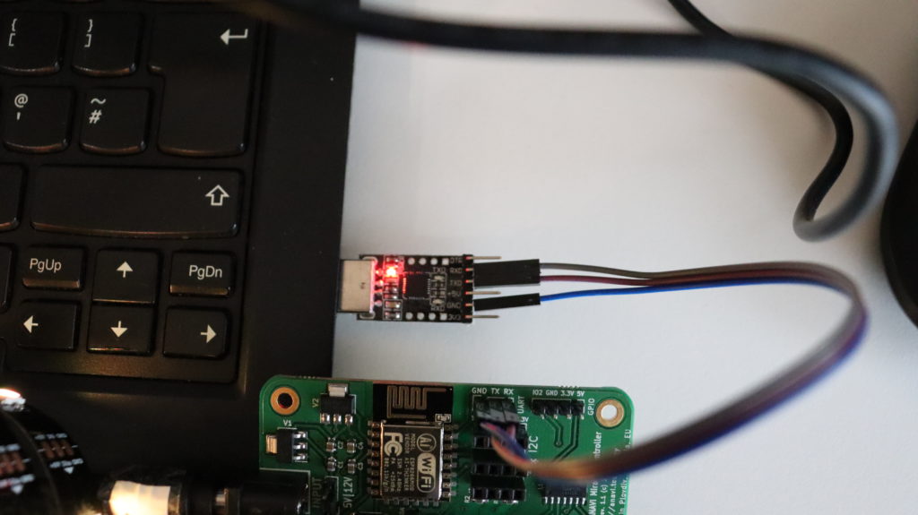
Each ANAVI Miracle Controller kit includes a USB to UART debug cable with CP2102. Depending on the operating system on your PC you might be required to install additional drives. It works out of the box on GNU/Linux distributions. As open source enthusiasts we are using it on Ubuntu. Plug the USB in your computer and connect the 3 wires as follows:

ANAVI Miracle ControllerUSB to UART Debug Cable
RXTX
TXRX
GNDGND
Connecting USB to UART cable to ANAVI Miracle Controller

Download Arduino IDE

Download and install Arduino IDE on your personal computer. It is free and open source software available for MS Windows, Mac OS and GNU/Linux distributions.

Launch Arduino IDE. From File > Open load an Arduino sketch. It can be the default firmware or any other compatible with ANAVI Miracle Controller Arduino sketch.

Configure ESP8266 in Arduino IDE

Go to File > Preferences. Select Settings and in the field Additional Boards Manager URLs add: http://arduino.esp8266.com/stable/package_esp8266com_index.json

From Arduino IDE select Tools > Board: Generic ESP8266 Module. Set the flash size to 4M (1M SPIFFS). The upload speed is 115200. Adjust the exact port of USB to serial debug cable connected to your computer.

Install Libraries

Select Tools > Manage Libraries. The Arduino library manager will appear. Install all required libraries and their exact versions. Over the time, with the development of the default firmware, new libraries might be added. Please have a look at the README file to get the up to date list of all Arduino libraries on which the the default firmware depends on.

Compile & Upload

In Arduino IDE click Verify/Compile. If there are any errors, please double check that you have installed all required libraries and their exact versions. If the source code compiles successfully, please proceed to to the next step for flashing the firmware.

Set the jumper to 5V or 12V depending on the type of addressable LED strip and power supply. Mismatch of the voltage may lead to severe hardware failure.

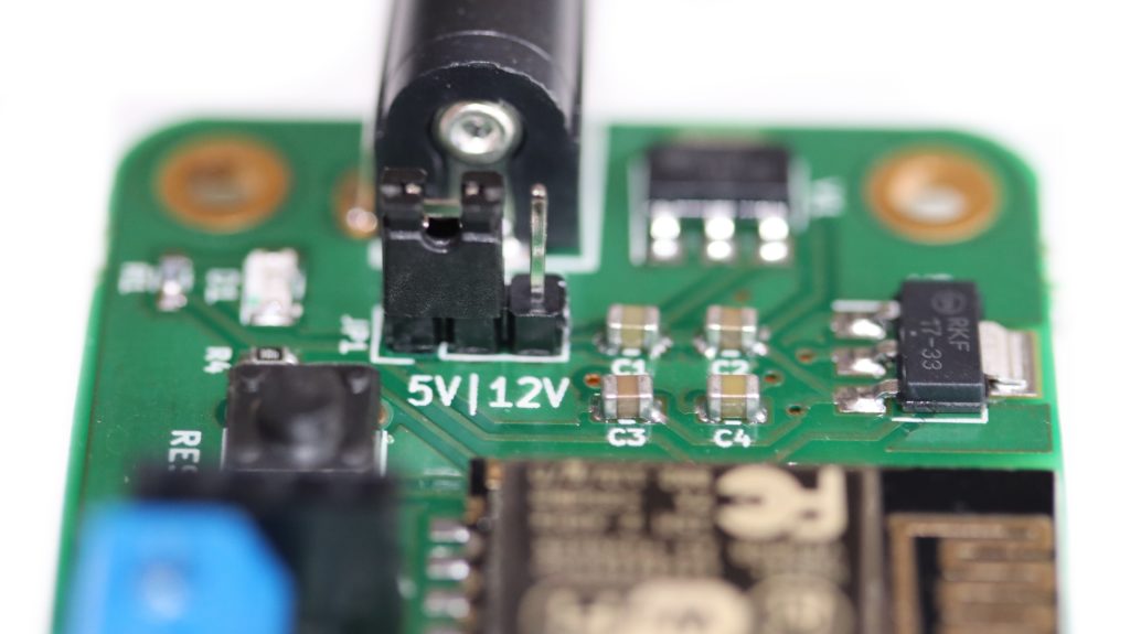
In Arduino IDE click Upload. Set the jumper on ANAVI Miracle Controller to 5V or 12V depending on your power supply and type of LED strips. The power supply voltage must match the required voltage by the LED strips, for example 5V for NeoPixels and the WS2812B included in all kits. Press and hold the RESET button on ANAVI Miracle Controller. Without releasing the RESET button, plug the power supply in the barrel jack of ANAVI Miracle Controller.

Do NOT release the RESET button until you see in Arduino IDE that the upload is 100% completed!

ANAVI Miracle Controller with 2 WS2812B LED strips connected to a laptop using USB to UART cable

You may also like

Improved Arduino Sketch for ANAVI Light Controller

How often do you get software or firmware updates for a 2-year-old device? Probably not very often. This is not the case for ANAVI Light Controller! We have a major update of its Arduino sketch for you.

ANAVI Light Controller

ANAVI Light Controller open source hardware WiFi device for controlling a 12V RGB LED strip. It was brought to life through a crowdfunding campaign at Crowd in 2018. Now is January 2020, so this makes it ~2 years old! A lot of things have changed during this time. ANAVI Light Controller has been certified by Open Source Hardware Association (OSHA) and it now on sale at our distributors: Crowd Supply, Pi Supply and neven.cz.

Terminals for connecting 12V RGB LED strip to ANAVI Light Controller

Recently we made a major improvements to the default firmware available as an Arduino sketch at GitHub:

  • Support Home Assistant automatic discovery over MQTT
  • Turn on LED D1 on ANAVI Light Controller if the device is not connected to local WiFi network and needs initial configuration
  • Wait for a few seconds while LED D1 is blinking immediately after turning on ANAVI Light Controller to allow reset by keeping SW1 pressed
  • Append the last 5 characters of the machine ID to the WiFi Access Point (AP) to simplify the identification of the ANAVI Light Controller during the initial setup
  • Support MQTT messages with large payload for reporting back the current state of the RGB LED strips on topic stat/dev-id/color
  • Add DEBUG macros, disabled by default, if enabled additional debug information will be printed in the serial monitor
Changing colors of 12V RGB LED strip through Home Assistant using ANAVI Light Controller

You can either compile and upload the new version through Arduino IDE or just grab the binary from GitHub and flash it on your ANAVI Light Controller.

To learn more how ANAVI Light Controller works out the box with the popular open source platform Home Assistant read our previous article. It reveals the exact steps the setup MQTT Broker in Home Assistant and after that to automatically discover ANAVI Light Controller.

ANAVI Light Controller is suitable for low-cost 12V analog (non-addressable) LED strips. If you need a WiFi development board for controlling digital (addressable) LED strips at 5V or 12V have a look at our other open source product ANAVI Miracle Controller.

You may also like

How to Use Mini Monochrome OLED I2C Displays (SSD1306)?

Mini monochrome OLED I2C displays are cheap, reliable and easy to use by makers. They come in a huge variety of sizes. Our open source hardware Internet of Things, like ANAVI Thermometer and ANAVI Gas Detector, support this type of display and all kits include a particular yellow-blue model that is a bit below 1”. The display has 4 mounting holes. The screen resolution is 128×64 pixels. The driver is SSD1306. You can find exactly the same type of display with only white OLED pixels. The usage is the same no matter what is the color of the OLED pixels.

ANAVI Thermomter with yellow-blue mini OLED I2C display

In this video tutorial you will learn the exact steps how to get started with I2C OLED mini display with about 1” diagonal on Arduino compatible board such as our ANAVI Thermometer. ANAVI Thermomter is an ESP8266-powered, open source, Wi-Fi dev board with temperature and humidity sensors.

Continue reading “How to Use Mini Monochrome OLED I2C Displays (SSD1306)?”

You may also like