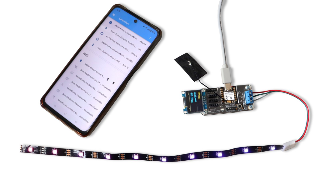
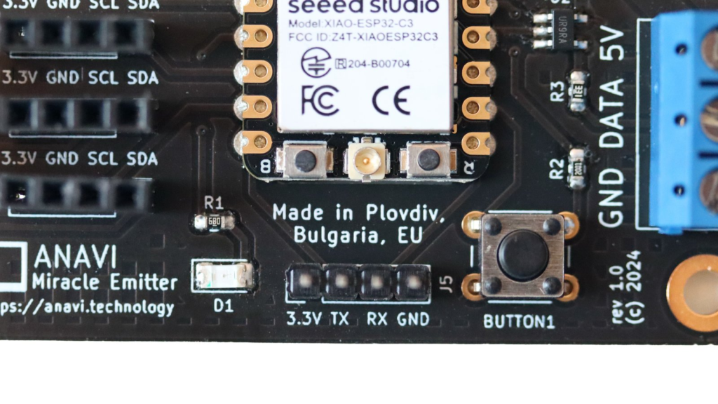
We are thrilled to announce the successful completion of our crowdfunding campaign at Crowd Supply for the ANAVI Miracle Emitter, which wrapped up on May 29th 2025. Your enthusiastic support made this possible – thank you! Backers from across seven different countries came together to champion this open-source development board designed for controlling NeoPixel LEDs, featuring the ESP32-C3 chip built on the open architecture RISC-V.
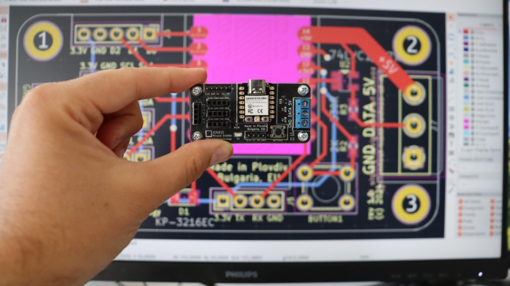
We’re happy to report that the project is progressing smoothly. All printed circuit boards have been produced and assembled, and the custom laser-cut acrylic cases are ready. We have also secured environmentally friendly packaging materials, including recyclable cardboard boxes and a fresh batch of stickers to add some flair.
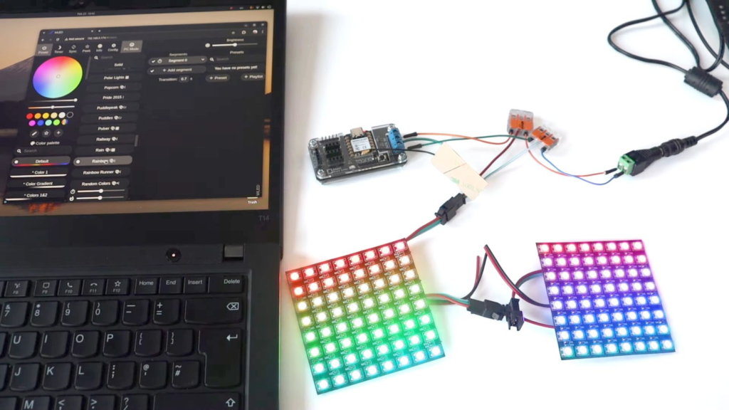
On the software side, version 1.0.1 of the default open-source firmware that works with Home Assistant over MQTT is now live and will be pre-installed on each unit. As always, the board’s fully open design means you can install alternatives like WLED or create your own custom firmware as you see fit.
In the coming days, we will complete the final packaging and deliver everything to the Crowd Supply warehouse in the US. Shipping to backers will begin shortly afterward, and your kits will be on their way!
We are incredibly grateful for your continued support, input, and engagement with our open-source GitHub repositories. More exciting news and updates are just around the corner so stay connected!
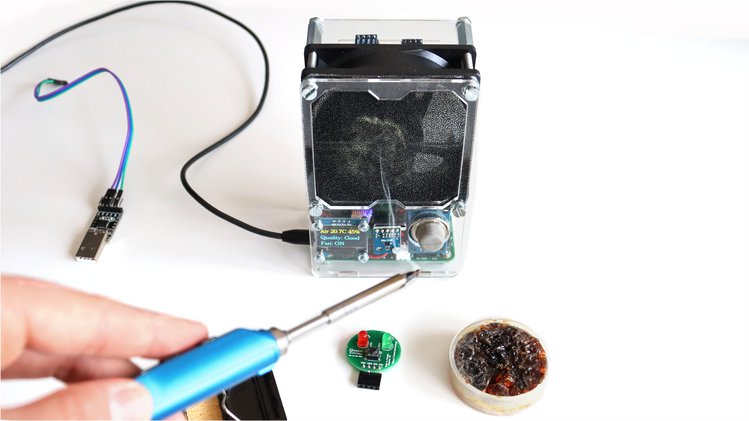
ANAVI Fume Extractor is an open source smart solder smoke absorber useful for makers during soldering. It comes as a do-it-yourself kit. There are 3 types of kits with different sensor modules. ANAVI Fume Extractor is available at Crowd Supply, Mouser and Tindie.
ANAVI Fume Extractor video assembly guidelines
This tutorial explains the exact steps of how to assemble the ANAVI Fume Extractor developer kit which contains all supported peripherals. The whole process can take up to 30-40min. A screwdriver is required. It is highly recommended to watch the video with the assembly guidelines before you start.
Step 1: Peel off the protective films
Each ANAVI Fume Extractor kit contains 4 acrylic enclosures. Peel off the protective films from both sides of all of them. The acrylic enclosure will be clear and transparent once the film is peeled off.
Step 2: PCB
Attach the ANAVI Fume Extractor printed circuit board to the bottom acrylic enclosure with 4 screws and 8 nuts. Add 4 nuts below and 4 nuts above the board.
Step 3: Mini OLED Display
The kit includes 4 M2 screws and nuts as well as appropriate washers. Remove the protective film from the mini I2C OLED display. Carefully attach the display to the front acrylic case as shown in the video. The display is fragile. Don’t fasten the screws too tight!
Step 4: Fan Filter
A couple of fan filters are included in each kit. Attach the 4 M4 screws to the front acrylic enclosure with 4 of the M4 nuts. Place one of the filters. Leave the other one as a replacement.
For long-term maintenance over time the filter must be regularly replaced. There is a huge variety of 80mm fan filters on the market. It is up to you to decide whether to buy carbon or HEPA filters. Various distributors offer appropriate filters, for example Mouser has 80 mm, 45 PPI foam media filters.
Step 5: Fan
Add the acrylic enclosure that separates the fan from the filter. On the side of the fan you will notice a label that indicates the direction of the air flow. Place the 80mm 5V DC fan so that the air will flow through the filter.
Screw the 4 M4 20mm stand-offs to firmly fix the position of the fan.
Step 6 (optional): Light Sensor Module
Owners of a developer kit should add the BH1750 light sensor module to the front acrylic enclosure and fix it with one M4 screw and a nut.
Step 7: Peripherals
Connect peripherals, like the fan and the mini OLED display, to the printed circuit board. There are dedicated connectors for both of them. Pay attention to the labels for I2C on the top of the mini OLED display.
Step 8 (optional): Sensors
Owners of advanced or developer kits should attach:
MQ-135 for indoor air quality
HTU21D I2C sensor module for temperature and humidity
BMP180 I2C sensor module for barometric pressure and temperature.
Step 9: Assemble all acrylic enclosures
Finally, assemble together all acrylic enclosures by fastening 4 M4 nuts on the back of ANAVI Fume Extractor.
On the right side of ANAVI Fume Extractor you will notice a jumper for the WiFi as well as a button to switch the filter on and off. By default the jumper for the WiFi is set to OFF. Move it to ON and power cycle the board if you want to connect ANAVI Fume Extractor to a MQTT broker and IoT platform such as the popular open source system Home Assistant.
To turn ANAVI Fume Extractor on, gently plug an appropriate cable and 5V power supply into the microUSB connector on the left side of the board. The microUSB connector is used only for providing power, no data is transferred. Power supply and microUSB cable are NOT included in any of the kits.
For advanced or developer kits, on the first boot, it is very important to do what is called the “burn-in” procedure for initial calibration of MQ-135 air quality sensor module:
Place ANAVI Fume Extractor with the attached MQ-135 in a room with clean air
Leave it running for at least 24 hours
This has to be done only once when the MQ-135 sensor module is used for the first time. After doing this procedure, on every next boot ANAVI Fume Extractor and MQ-135 will do a quick calibration in a couple of minutes and start working properly.
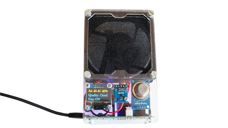
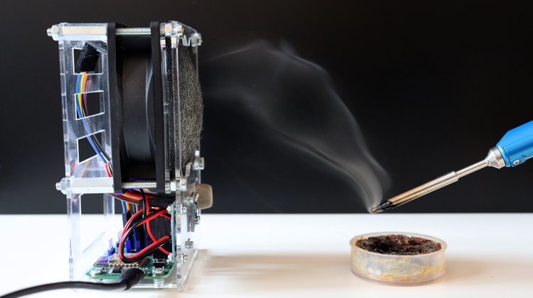
ANAVI Fume Extractor is a smart, open source, solder smoke absorber. It is powered by ESP8266 with WiFi, 80 mm fan and supports various peripherals: mini OLED display, MQ-135 analog gas sensor for air quality, sensors for temperature, humidity, barometric pressure and light. The filters are replaceable.
Soldering fumes are dangerous, keep them away with ANAVI Fume Extractor
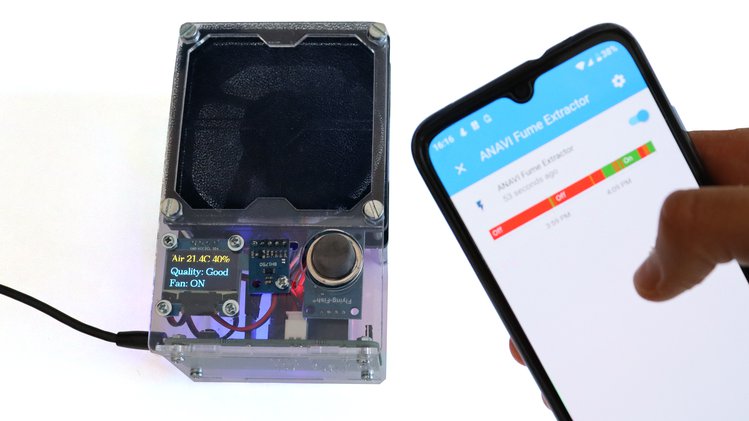
Furthermore out the box the open source firmware of ANAVI Fume Extractor works with the popular IoT platform Home Assistant over the protocol MQTT. This means you can gather sensor data and control the fume extractor remotely using your smartphone, tablet or personal computer!
Turning on and off ANAVI Fume Extractor from a smartphone using Home Assistant
After more than 10 months of development we launched a crowd funding campaign at Crowd Supply! We are ready for manufacturing in Plovdiv, Bulgaria and now we need your support. We hope you’ll jump in and help us bring this entirely open source project to life!
ANAVI Fume Extractor is a must-have tool for any maker!
ioBroker is an open source Internet of Things platform written in JavaScript and using Node.js for the back-end. It is perfect to run on single board computers such as Raspberry Pi. The project started in 2014. The source code is hosted in GitHub and the core is available under MIT license. The creators and maintainers of ioBroker are from Germany and the project is very popular among the German open source community interested in home automation.
In this article you will learn how to get started with ioBroker by installing it on a Raspberry Pi and after that how to measure temperature and humidity from the built-in DHT22 sensor on ANAVI Thermometer through the machine-to-machine protocol MQTT.
ioBroker Installation Guide
Step by step video tutorial for installing ioBroker on Raspberry Pi
Only two steps are required to install ioBroker on GNU/Linux distributions, including on a Raspberry Pi with Raspbian:
After successfully installing ioBroker, open the web interface and complete the initial setup as explained in the video.
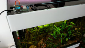
Monitoring Temperature and Humidity from DHT22 in ioBroker via MQTT
Integrating ANAVI Thermometer with DHT22 temperature and humidity sensor in ioBroker
ANAVI Thermometer is an open source hardware, Wi-Fi development board for measuring temperature that’s powered by an ESP8266 processor. It comes with a built-in DHT22/AM2302 temperature and humidity sensor and has slots for a mini OLED display, waterproof DS18B20 temperature sensor, and empty slots for up to three additional I2C sensor modules. Out of the box, the open source firmware of ANAVI Thermometer, works with Home Assistant specification for automatic discovery and MQTT messages with JSON payload.
Although ioBroker is an alternative open source IoT platform, through an adapter it supports the Home Assistant specification. The process for using ANAVI Thermometer in ioBroker is straight-forward thanks to the adapters MQTT Client/Broker and HASS-MQTT.
Adapter MQTT Client/Broker can be configured either as MQTT broker or as a client mode and use an external broker. In the particular demonstration in the video the instance of ioBroker adapter MQTT Client/Broker has been configured as a broker, without username/password and with disabled publish check-boxes from the MQTT Settings tab.
Adapter HASS-MQTT is required to support the Home Assistant MQTT specification. It have to be installed separately and bound to the instance of adapter MQTT Client/Broker as shown in the video. Get the HASS-MQTT adapter from: https://github.com/smarthomefans/ioBroker.hass-mqtt
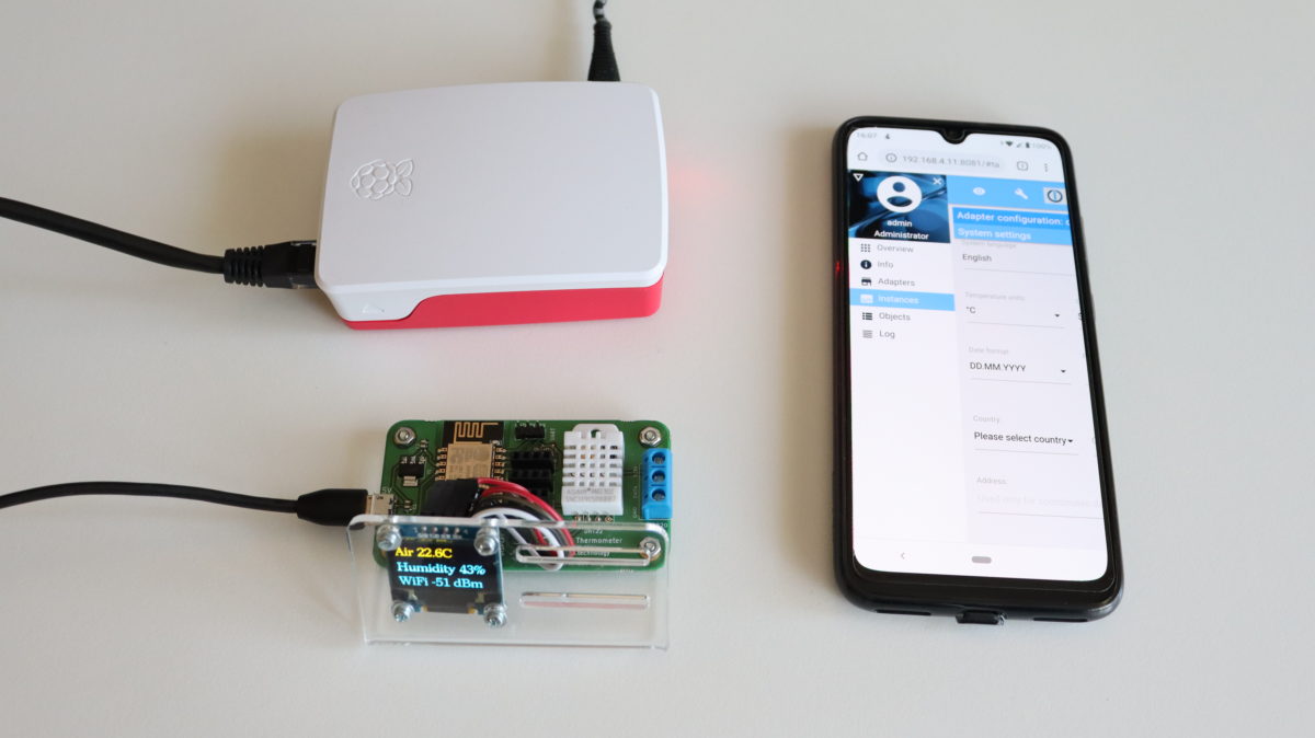
ANAVI Themometer reporting temperature and humidity to the open source IoT JavaScript platform ioBroker
After turning on the instances of both adapters in Home Assistant, ANAVI Thermometer must be configured to connect to the same MQTT broker. After that ANAVI Thermometer will be automatically detected and the data from DHT22 as well as from any other attached supported sensors will be automatically reported to ioBroker. You just need to configure how to display it in your preferred graphical user interface (ioBroker offers several of them). In the video I used the ioBroker visualisation adapter which requires activation through an unique key. The activation requires registration with a email and is not shown in the video. Adapter visualisation if free for personal use. The other adapters, MQTT Client/Broker and HASS-MQTT are free and open source without any limitations.
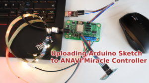
How often do you get software or firmware updates for a 2-year-old device? Probably not very often. This is not the case for ANAVI Light Controller! We have a major update of its Arduino sketch for you.
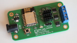
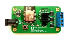
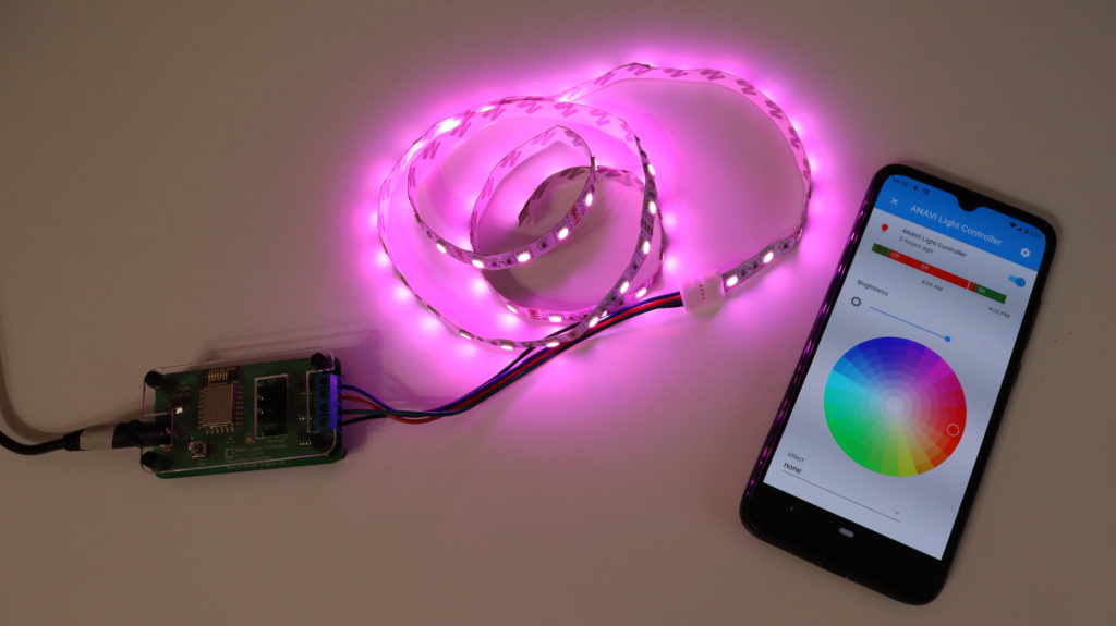
ANAVI Light Controller
ANAVI Light Controller open source hardware WiFi device for controlling a 12V RGB LED strip. It was brought to life through a crowdfunding campaign at Crowd in 2018. Now is January 2020, so this makes it ~2 years old! A lot of things have changed during this time. ANAVI Light Controller has been certified by Open Source Hardware Association (OSHA) and it now on sale at our distributors: Crowd Supply, Pi Supply and neven.cz.
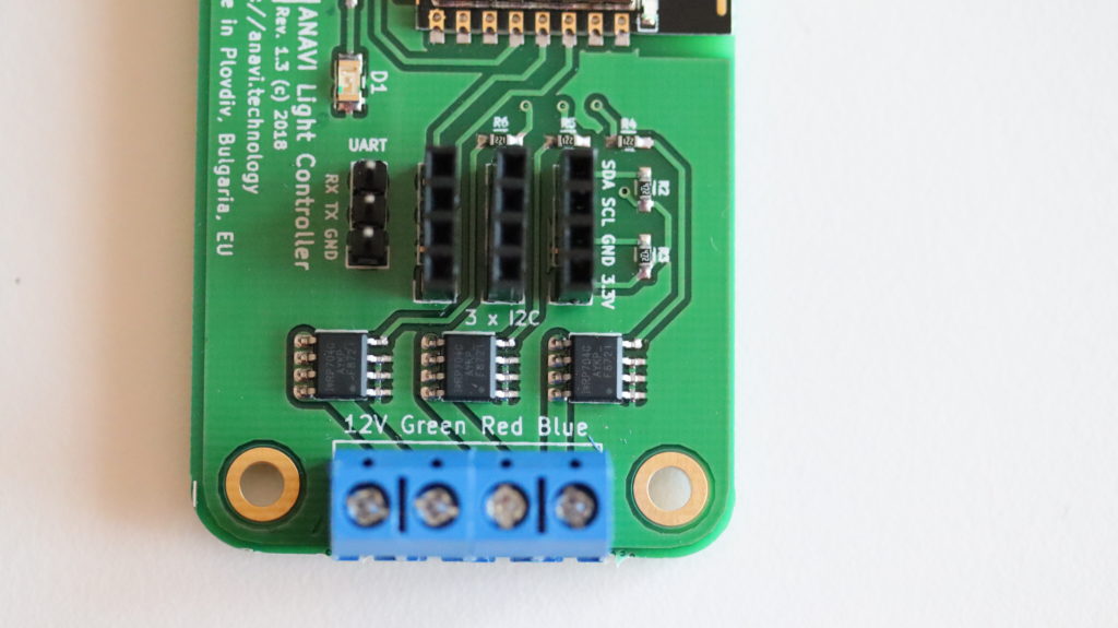
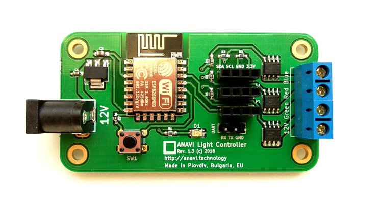
Terminals for connecting 12V RGB LED strip to ANAVI Light Controller
Support Home Assistant automatic discovery over MQTT
Turn on LED D1 on ANAVI Light Controller if the device is not connected to local WiFi network and needs initial configuration
Wait for a few seconds while LED D1 is blinking immediately after turning on ANAVI Light Controller to allow reset by keeping SW1 pressed
Append the last 5 characters of the machine ID to the WiFi Access Point (AP) to simplify the identification of the ANAVI Light Controller during the initial setup
Support MQTT messages with large payload for reporting back the current state of the RGB LED strips on topic stat/dev-id/color
Add DEBUG macros, disabled by default, if enabled additional debug information will be printed in the serial monitor
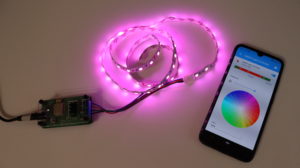
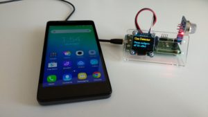
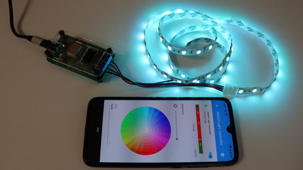
Changing colors of 12V RGB LED strip through Home Assistant using ANAVI Light Controller
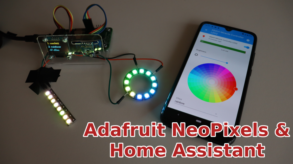
Yes, that’s correct! Let’s get started with Adafruit NeoPixel Ring and NeoPixel Stick in Home Assistant without any coding, just a few simple configurations.
Install Mosquitto MQTT broker from Hass.io add-on store, configure username and password as well as Access Control Lists (ACL).
From Configure > Integrations add new MQTT integration and click Enable discovery. It is mandatory to enable discovery!
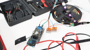
Solder male to male jumper wires to Adafruit NeoPixel Ring and NeoPixel Stick.
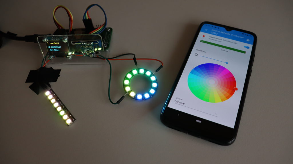
Connect NeoPixel Stick DIN to LED1, GND to GND and 5VDC to VOUT on ANAVI Miracle Controller. Connect NeoPixel Ring Data Input to LED2, GND to GND and 5V DCPower to VOUT on ANAVI Miracle Controller.
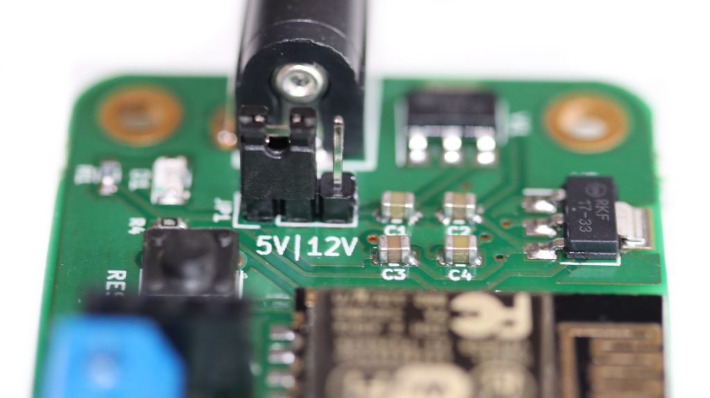
Set the jumper of ANAVI Miracle Controller to 5V and use appropriate power supply to turn on the board.
Configure ANAVI Miracle Controller to connect to your local WiFi network, set LED type to NEOPIXEL, number of LEDs for LED1 to 8 and number of LEDs for LED2 to 12.
In Home Assistant web interface, a couple of new devices will be automatically added under the names ANAVI Miracle Controller LED1 and ANAVI Miracle Controller LED2. Set different effects and colors for each Adafruit NeoPixels.
How Does It Work?
ANAVI Miracle Controller combines open source hardware with free and open source software. It has been certified by the Open Source Hardware Association under UID BG000050. After initial configuration the default firmware of ANAVI Miracle Controller, available as an Arduino sketch in GitHub, connects to the WiFi network and the MQTT broker. It sends a retained MQTT message with JSON payload containing description of the device. Home Assistant, thanks to the MQTT integration with enabled discovery, automatically receives the message and recognizes the device as MQTT Light component. As a result out of the box ANAVI Miracle Controller appears in the Home Assistant GUI.
Home Assistant is a popular open source platform for home automation. It is written in Python programming language and runs perfectly on Raspberry Pi 3 B/B+ or 4 B. Now, with the latest updates of the Arduino sketch for ANAVI Light Controller it is super easy to control 12V RGB LED strip from Home Assistant through your smartphone, tablet or personal computer.
Have a look at the video and follow the steps below to configure ANAVI Light Controller and change colors of 12V RGB LED strips from Home Assistant.
Install Mosquitto from Hass.io add-on store. Set username and password for login to Mosquitto. Set active Access Control Lists (ACL) for the username and launch Mosquitto (it is recommended to install SSH server prior this step).
Add MQTT integration in Home Assistant with enabled discovery (from Configuration > Integrations)
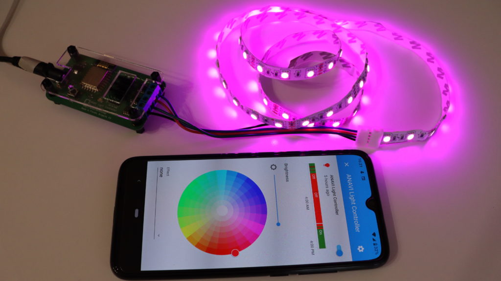
Attach the 12V RGB LED strip to ANAVI Light Controller
Turn on ANAVI Light Controller, connect to its WiFi Access Point (AP) and configure it through the captive portal. You must provide your WiFi credentials, MQTT server, username and password. After that ANAVI Light Controller will be automatically discovered by Home Assistant over MQTT.
Through Home Assistant change colors or effects of ANAVI Light Controller.
As soon as ANAVI Light Controller boots, after it has been configured, it connects to the WiFi network, after that to the MQTT broker and sends retained MQTT message with JSON payload that describes the device. Each ANAVI Light Controller has a unique MD5 ID based on the chip ID of ESP8266. The MQTT integration in Home Assistant discovers ANAVI Light Controller based on the received MQTT message. Thanks to the data in the JSON payload Home Assistant automatically configures the device as MQTT Light.
Home Assistant & 12V RGB LED strip attached to ANAVI Light Controller
Home Assistant discovery is a user-friendly way for quickly adding new Internet of Things to the platform. Combined with MQTT and the default firmware for ANAVI Light Controller the process is straight-forward and anyone can do it in a few minutes.
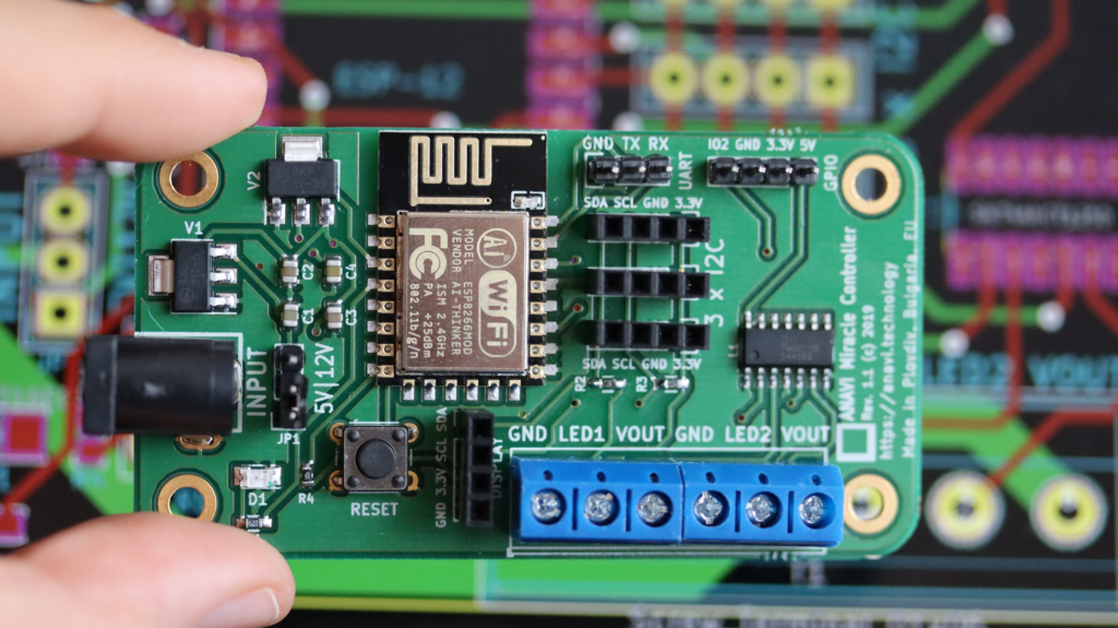
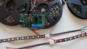
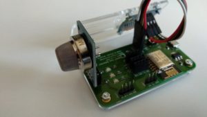
ANAVI Miracle Controller is an open source hardware Wi-Fi development board powered by the ESP8266 and designed to control two 5 V or 12 V addressable LED strips simultaneously.
ANAVI Miracle Controller supports popular addressable LEDs including Neopixel, WS2811, WS2812B, TM1809, etc. It also has a dedicated slot for a mini OLED I²C display and slots for up to three additional I²C sensor modules. The default firmware is available at GitHub as an Arduino sketch implementing Home Assistant MQTT Light component.
Back in 2018 we created ANAVI Light Controller for low-cost 12V RGB LED strips. Inspired by a lot of people asking for open source hardware dev board for addressable LEDs strips we created ANAVI Miracle Controller.
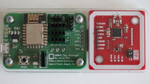
ANAVI Light Controller is a certified open source hardware WiFi dev board for controlling a 12 V RGB LED strip. Furthermore it has 3 slots for attaching I2C devices, for example sensors for temperature, humidity barometric pressure, light, mini OLED display, etc.
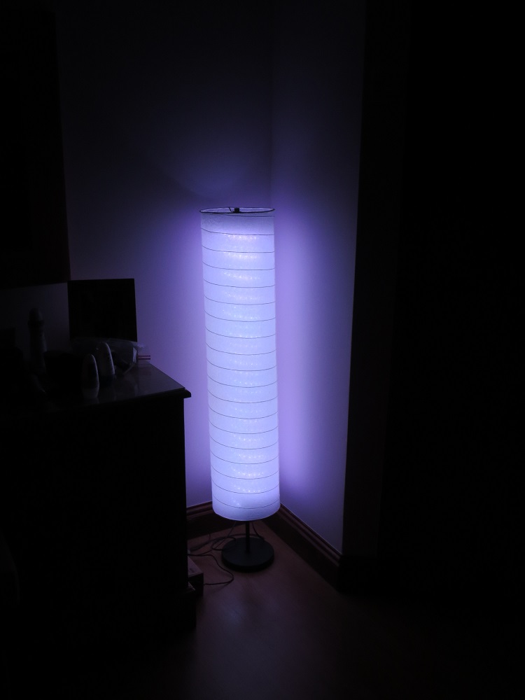
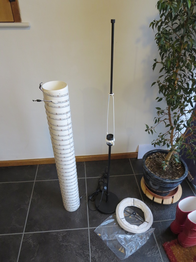
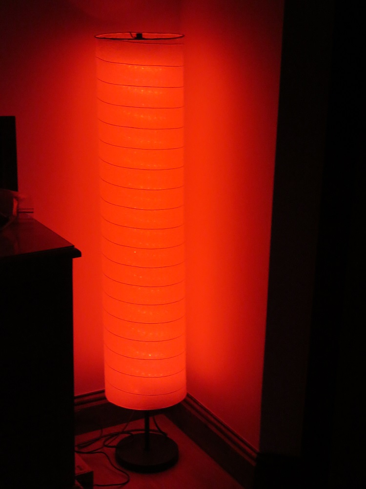
The hardware required for Jonathan’s project includes a Raspberry Pi, ANAVI Light Controller, 12V RGB LED strip, appropriate power supplyies and appropriate lamp. Jonathan used IKEA Holmo floor standing lamp and placed RGB LED strips around a suitable tube inside it. The software requirements are JAVA 8 or above as well as an MQTT broker, for example the free and open source mosquitto.
ANAVI Gas Detector is an ESP8266-powered, open source, Wi-Fi dev board for monitoring air quality and detecting dangerous gases. In the previous blog post I have shared the exact steps how to assemble it. Now I will cover the straight-forward process for connecting it to your Wi-Fi network. It is very simple and takes less than a couple of minutes.
Step 1: Turn on ANAVI Gas Detector
When you turn on ANAVI Gas Detector for the first time, it will create its own Wi-Fi Access Point with the name ANAVI Gas Detector followed by a unique five character ID.
These characters are actually the end of the MD5 hash generated from the unique chip ID of the ESP8266 module. To avoid confusion, the same five characters are showed on the mini OLED display included in all kits of ANAVI Gas Detector.
Connect to the Wi-Fi access point created by ANAVI Gas Detector from your smartphone, tablet or personal computer.
Step 2: Captive Portal
Once you have connected to the Wi-Fi access point created by ANAVI Gas Detector, a captive portal will pop-up and guide you to the next steps. Click Configure WiFi as shown in the video.
Step 3: Configure
Select your local Wi-Fi network, enter a password (if it is not open), type in MQTT broker address, port, username and password.
By default, just for demo purposes, ANAVI Gas Detector connects to iot.eclipse.org with port 1883 and no username/password. This is a public MQTT broker just for demonstrations. It is highly recommended to install open source MQTT broker locally and connect ANAVI Gas Detector to it.
Optionally, you can also select a temperature scale. By default it is set to Celsius. Of course, Fahrenheit is also supported. To switch just type in fahrenheit.
Finally, when ready, just click Save. ANAVI Gas Detector will reboot and try to connect first to your Wi-Fi network and after that to the configured MQTT broker. If it experience problems connecting you will be asked to do the configuration again.
That’s it! The whole process requires just these three easy steps and takes less than a couple of minutes. No need to download & install any apps on your smartphone. If you don’t have a smartphone – you can do the configuration from your personal computer or a tablet.
One More Thing…
Once ANAVI Gas Detector is up and running, if you need to change the configurations, just press and hold the RESET button on the board for 10 seconds. Keep the RESET button pressed until the D1 indication LED on the board is blinking.
This way you will wipe out all configuration, reset ANAVI Gas Detector to factory default and you will be asked to connect it again to your Wi-Fi.