As part of the covered stretch goals, each kit will include stickers from ANAVI Technology and KiCad, the free and open source CAD software used for designing the printed circuit boards of the keyboards. Furthermore, ANAVI Macro Pad 10 kits will include 32 super-cool emoji stickers. You can stick them on the top or sides of the translucent keycaps. Last but not least, we’ll be publishing various video tutorials to ensure getting started is easy.
One more thing… Recently, our mini mechanical keyboards were featured in an article by CNX Software. This is a very popular website with news and tutorials about embedded systems, makers, and open source hardware. It was started in 2010 by Jean-Luc Aufranc. By the way it is worth keep an eye on CNX Software because there are always news about interesting gadgets!
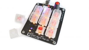
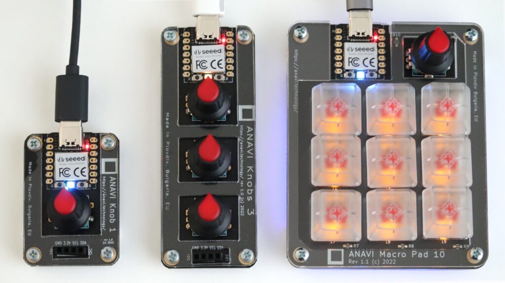
ANAVI Knob 1, ANAVI Knobs 3 and ANAVI Macro Pad 10
ANAVI Macro Pad 10, ANAVI Knobs 3 and ANAVI Knob 1 all come with gold-plated black printed circuit boards, Raspberry Pi RP2040 microcontrollers, USB-C connector and clickable rotary encoders. The popular open source KMK firmware allows you to easily program and configure custom keyboard layouts and macros using CircuitPython.
The printed circuit boards still on panels before adding the EEPROM
The printed circuit board of ANAVI Info uHAT has a green solder mask and a gold surface finish. There are a few steps more to complete the manufacturing process. An EEPROM has to be flashed and soldered on each board. It will contain software description of the add-on board following Raspberry Pi Foundation’s HAT (Hardware Attached on Top) specifications. After that each board will go through a quality assurance, and finally each kit will be packaged in a recyclable cardboard box.
Panels with ANAVI Info uHAT
Low-volume manufacturing is not an easy task nowadays, especially during a global chip shortage. As usual we will keep you updated. Thank you again for supporting ANAVI Info uHAT!
I2C stands for Inter-Integrated Circuit, pronounced eye-squared-C, and alternatively known as IIC. It is a synchronous, multi-controller/multi-target (controller/target), packet switched, single-ended, serial communication bus. This protocol is suitable for devices wired at short distances, no more than 2-3m. We use I2C in pretty much all our open source products: Internet of Things, mechanical keyboards and Raspberry Pi HATs.
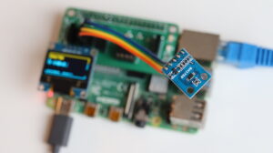
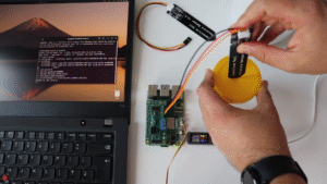
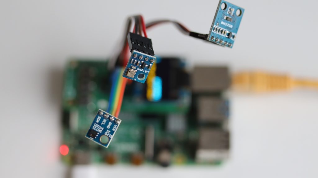
I2C sensor modules attached to ANAVI Info uHAT
I2C was originally developed in 1982 by Philips. While that makes it 40 years old, it is still a very convenient and widely used bus. There are many I2C sensors and peripherals. It is in pretty much every smartphone, embedded electronics, microcontroller, personal computer and of course Raspberry Pi.
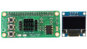
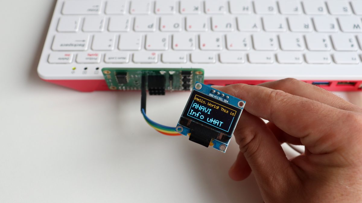
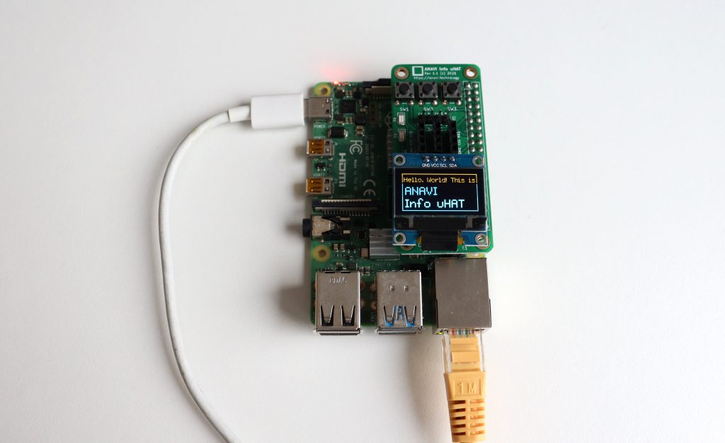
ANAVI Info uHAT with 4 slots for I2C sensors and mini OLED dsiplay
Actually, since the introduction of the famous 40-pin header in 2014, Raspberry Pi single board computers have not one but two I2C buses! We use them both on ANAVI Info uHAT and our other HATs. Th first I2C bus is on pins 3 and 5. On the ANAVI Info uHAT, it is used for the three I2C slots for sensors and the 4th dedicated slot for the mini OLED display.
The I2C bus on ANAVI Info uHAT in KiCad’s Schematic Layout Editor.
The second I2C bus is on pins 27 and 28 of the Raspberry Pi and is reserved exclusively for attaching an ID EEPROM. The ID EEPROM contains a software description of the hardware so the operating system on your Raspberry Pi can automatically identify the add-on board.
The EEPROM on ANAVI Info uHAT attached on the 2nd I2C bus
The I2C bus consists of two signals: SDA (Serial Data) is a data signal, SCL (Serial Clock) is a clock signal. I2C modules also need power, so the dedicated I2C connectors on the ANAVI Info uHAT and our other open source hardware provide two additional pins for VCC and GND. Typically, the VCC for the I2C connectors on our add-on boards for Raspberry Pi are 3.3V.
The I2C bus drivers are “open drain”, which means they can only pull the corresponding signal line at low level. They cannot drive it high. To restore the signal to high when no device is asserting it low, a pull-up resistor has to be added to each signal line. For example, on the ANAVI Info uHAT, we have 4.7K pull-up resistors R4 and R5 connected to SDA and SCL.
Resistor selection varies depending on the devices attached to the bus. In some specific use cases, further adjustment of the resistance value might be required. For systems with lots of devices or longer wires, smaller resistors are better.
How to Enable I2C on Raspberry Pi OS
Raspberry Pi OS, previously known as Raspbian, is the default and recommended Linux distribution for all models and versions of the Raspberry Pi single board computer. By default, I2C is not enabled. There are several ways to enable it, but probably the easiest is using the command-line tool raspi-config to perform few basic commands:
Open a terminal or login remotely via SSH to your Raspberry Pi and type in the following command: sudo raspi-config
Each I2C device must have a unique address. The I2C reference design has a 7-bit address space, although rarely it might be used with a 10-bit extension. The 7-bit addresses range from 0 to 127 (0 to 0x7F hexadecimal). This is a limitation because it is not possible to have two I2C devices with the same address on the same I2C bus. For example, the I2C address on the mini OLED display included in all ANAVI Info uHAT kits is 0x3C. From the software side, this address is used in the example Python 3 script to access the display.
Python3 script controlling the mini OLED display over I2C on ANAVI Info uHAT
For Linux distributions, including Raspberry Pi OS, there is a package with a heterogeneous set of I2C tools called i2c-tools. To install it on Raspberry Pi OS, open a terminal and execute: sudo apt install -y i2c-tools. Once you have it installed, you can list attached I2C devices by their addresses with i2cdetect. For example, if the HTU21 temperature and humidity sensor module is attached to the Raspberry Pi, the output will be:
The event was organized by OPENNEXT. This is an organization that aims to bring together SMEs and makerspaces across the European Union (EU) to develop new hardware products based on open-source principles. The event brought together representatives of the Technical University Berlin, the Grenoble Institute of Technology, the University of Bath, the DDC – Danish Design Center, and many more organizations involved with open source software and hardware. Lukas Hartmann, the creator of the open source DIY laptop MNT Reform, was also a panel speaker at the event.
Panel discussion during OPENNEXT event in the Technical University of Berlin
OSHWA runs the certification program ensures that the definition of “open source hardware” used by a specific project matches the community’s definition of open source hardware. They provide a unique indentification (UID) for each version of the certified hardware based on the country code and a serial number. For example, the UID for ANAVI Info uHAT is BG000081. The prefix BG is the country code for Bulgaria, because the Info uHAT is made in my hometown of Plovdiv. The serial numbers show that now there are 81 open source hardware devices from Bulgaria.
Thanks to early backers ANAVI Info uHAT was successfully funded and hit its first stretch goal in a just a couple of days. So we’ll be adding some awesome KiCad and ANAVI Technology stickers. KiCad is the free and open source software we used to design this and other Anavi printed circuit boards.
As a small open source project, ANAVI Info uHAT relies on the community of passionate open source makers. We are near our second stretch goal of $1,000. If we hit it, we will make more video tutorials for all supported sensors.
There is still more than a month until the end of the crowdfunding campaign and we hope more people will jump in and order ANAVI Info uHAT!
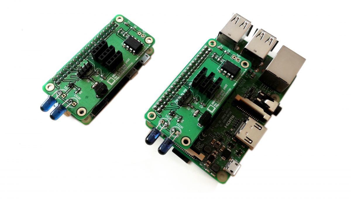
How to build an air quality monitor using Raspberry Pi Zero W + ANAVI Infrared pHAT
MH-Z19B is an intelligent infrared CO2 module which interacts with the Raspberry Pi using UART (universal asynchronous receiver-transmitter). Takuya uses the UART port on ANAVI Infrared pHAT to attach MH-Z19B. The rest of the sensor modules for his setup are included in ANAVI Infrared pHAT Advanced kit: HTU21D for temperature and humidity, BMP180 for barometric pressure and BH1750 for light.
By the way, initially we had published open source examples for using HTU21D, BMP180 and BH1750 in the C programming languages using the library wiringpi. Takuya also based his setup on wiringpi. However, wiringpi is now deprecated therefore we have replaced it with another library called libi2c-dev. Furthermore we added examples written in Python 3.
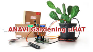
Earlier in January all ANAVI Gardening uHAT kits were delivered to the Crowd Supply warehouse and soon after that Crowd Supply team sent them to their final destination: our valuable and trusting crowdfunding backers! Thank you again for the support.
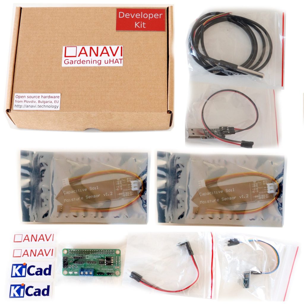
ANAVI Gardening uHAT Developer Kit
ANAVI Gardening uHAT is a versatile development board, so please follow the instructions below for safe use:
ANAVI Gardening uHAT should only be connected to a compatible Raspberry Pi with 40-pin header.
Do not expose it to water or moisture, and do not place it on a conductive surface whilst in operation.
Do not expose it to heat from any source; it is designed for reliable operation at normal room temperatures.
Take care while handling the board to avoid mechanical or electrical damage to the printed circuit board and connectors.
Avoid handling ANAVI Gardening uHAT while it is powered on. Only handle by the edges to minimize the risk of electrostatic discharge damage.
In the meantime, there is a work in progress going on the user’s manual which is available at GitHub. We will soon update it. As usual, GitHub pull requests with improvements and fixes to the documentation or the source code examples are always welcome.