The crowdfunding campaign for ANAVI Fume Extractor in Crowd Supply has been very successfully so far so we have already contacted suppliers and started sourcing various components. Most of the mechanical parts have already been delivered and we can have a closer look at them.
As some of you know, we will make and assemble the printed circuit boards in my beautify hometown of Plovdiv, Bulgaria. One of our goals is to support local manufacturing and if possible purchase parts from local factories and suppliers even when their prices are not the best. Of course, ANAVI Fume Extractor contains a lot of parts and some are so specific that nobody manufactures them locally. Because of this the project also relies on trusted suppliers from the US, the UK, Germany, Poland and China.

Transparent Acrylic Enclosures
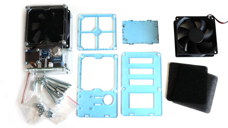
Each kit of ANAVI Fume Extractor contains 4 transparent acrylic enclosures. They have been designed with the free and open source tool OpenSCAD. The source and the schematics are available in GitHub. For the laser cutting I rely on a local Bulgarian company from Stara Zagora.
There are protective films on both sides of each acrylic enclosure. You must carefully remove them before assembly your do-it-yourself kit with ANAVI Fume Extractor.
Screws, Nuts and Stand-offs

ANAVI Fume Extractor contains various screws, nuts and washers for attaching the printed circuit board, the fan, the display and the sensor modules. The most difficult-to-source part is the 20mm M4 metal stand-off. Each kit contains 4 of them. We couldn’t find anyone in Bulgaria making stand-offs with the required size, so through a local supplier we imported the “abstandsbolzen” from Germany.

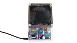
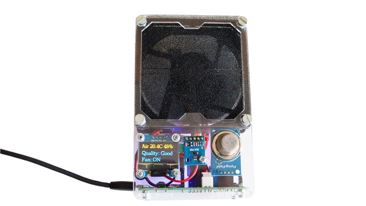
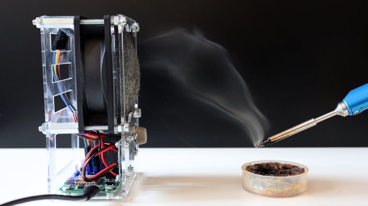
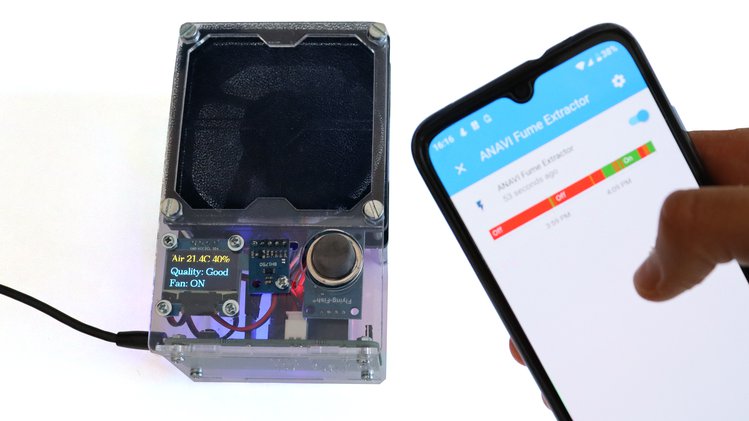
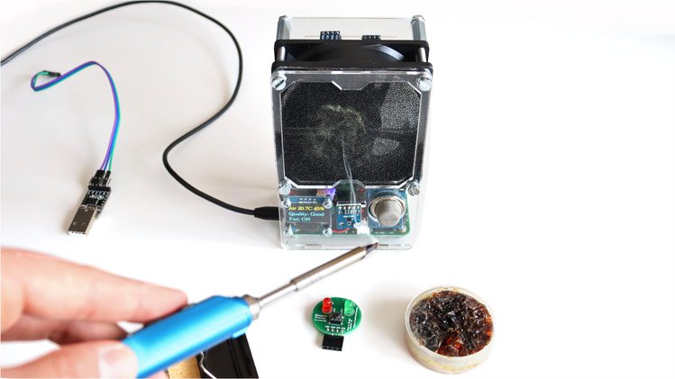
80mm Fan

The key part of ANAVI Fume Extractor is the 80mm 5V/0.25A brushless DC fan. This type of a fan is primarily used in personal computers which makes it relatively quite and compact. Unfortunately, this is another part that nowadays nobody makes in Bulgaria so we are importing it from China.
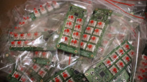
Packaging
All kits will come in an eco friendly recyclable cardboard box made in another Bulgarian town Lyaskovets. Although we do our best to reduce plastic packaging as much as I can, some small plastic bags made in Veliko Tarnovo, Bulgaria are still required to store the components in the kit. The stickers will be printed in Plovdiv.

The next step is the manufacturing of the printed circuit boards. Numerous components from various suppliers all around the world have to be assembled on the PCB. We will make it in a small local factory in my hometown of Plovdiv, Bulgaria. The manufacturing is scheduled to start right after the end of the campaign when we know the exact quantities.
Thank you for supporting entirely open source projects like ANAVI Fume Extractor!