ANAVI Macro Pad 8 Manufacturing Progress

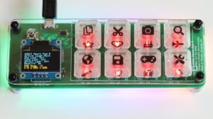
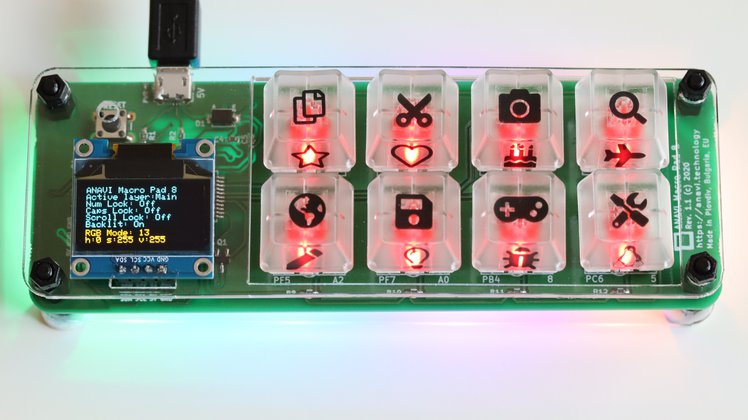
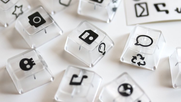
ANAVI Macro Pad 8 is an open source, programmable, eight-key keypad with backlighting, underlighting, and OLED screen. Following the successful crowdfunding campaign we manufactured the printed circuit boards in a small local factory in Plovdiv, Bulgaria, EU. We would like to explain in detail the whole manufacturing process.

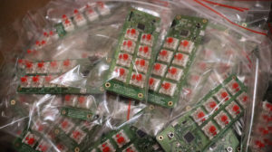
The fabrication includes a procedure called panelization which groups together a number of PCBs on a larger board called a “panel”. In the case of ANAVI Macro Pad 8 the “panel” contains 3 boards. All of them are gold plated through electrolytic nickel-gold process. Gold is very expensive, especially at the moment, but it is still worth it. Gold-plated PCBs have excellent quality with high hardness, wear and oxidation resistance.

A panel with 3 printed circuit boards for ANAVI Macro Pad 8

Sourcing parts in the COVID-19 time is a challenge but we work with trusted and reliable suppliers. We bought Microchip ATmega32U4 microcontrollers from Mouser. They arrived from the warehouse in Texas, USA. Each microcontroller is with TQFP-44 package that requires surface mount technology (SMT). The local factory has already assembled them alongside with all other SMT components.

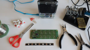
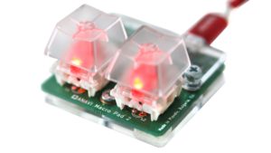
The assembly of Gateron red mechanical switches and the red 3mm LEDs for all developer kits requires through-hole technology, a.k.a. manual soldering. This is a time consuming process. To simplify the work and to keep the mechanical switches on their places we created this plate that matches the size of the panels.

There are special holes on each mechanical switch for the 3mm LED. After soldering all of them, the leads of the LEDs have to be cut from the back side of the panel.

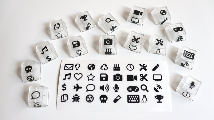
After all these steps, testing and packaging the developer kit will not require any soldering. However, people who enjoy soldering like me can order a maker kit and experiment with various mechanical switches and 3mm LEDs with different colors. Furthermore, the maker kit allows to perform a hot-swap upgrade as explained in the previous post.

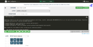
After burning a the same bootloader as in Arduino Leonardo, flashing the open source QMK firmware and testing our mechanical keyboards are ready for packaging!

ANAVI Macro Pad 8 Developer Kit
ANAVI Macro Pad 8 Maker Kit

You may also like

ANAVI Macro Pad 8 – (Not) Yet Another Mechanical Keyboard

After several months of development, the crowdfunding campaign for ANAVI Macro Pad 8 has been launched at Crowd Supply!

ANAVI Macro Pad 8

ANAVI Macro Pad 8 is an open source, programmable, eight-key mechanical keyboard with backlighting, underlighting, and OLED screen. The popular open source QMK firmware allows you to easily configure custom keyboard layouts and macros, even directly in a web browser.

The crowdfunding campaign has a very modest goal of just $1. We have 3 stretch goals! If we raise $500 or more we’ll add super cool 32 transparent emoji keyboard stickers to all kits. You can stick them to the top or the sides of the key caps.

Transparent stickers for the translucent keycaps on ANAVI Macro Pad 8

The crowdfunding campaign will help us manufacture it in a local factory in Plovdiv, Bulgaria, EU. We hope you’ll jump in and help us bring this entirely open source project to life!

You may also like

ANAVI Smiley and ANAVI Tag Manager Certified by the Open Source Hardware Association

The primary goal of ANAVI Technology Ltd. is to combine open source hardware with free and open source software. So far numerous of our development boards have been certified by the Open Source Hardware Association (OSHWA). In February 2020 a couple new products were also certified: ANAVI Smiley and ANAVI Tag Manager. Both of them have been designed with the free and open source tool KiCad.

A lot of products on the market claim their are open source hardware, however this is not always true. Open Source Hardware certification allows the community to quickly identify hardware that truly complies with the definition of open source hardware. Because of this certification by OSHWA is important for us.

ANAVI Smiley

Image
ANAVI Smiley add-on board for Raspberry Pi as a soldering kit

ANAVI Smiley is a simple add on for Raspberry Pi that comes as a soldering kit. It has a couple of LEDs and a button. A simple Python 3 application for using this add-on board is available at GitHub. ANAVI Smiley was certified by OSHWA with UID BG000061. It has been designed as a prize for the teams competing at Pi Wars 2020. Soon ANAVI Smiley will be also available on sale at tindie.

ANAVI Tag Manager

Image
ANAVI Tag Manager with PN532 NFC RFID module and an acrylic enclosure

ANAVI Tag Manager is a WiFi development board for using PN532 NFC RFID module. The board is using ESP8266. It is powered from microUSB connector. There are slots for UART pins, mini OLED display and up to 3 I2C sensor modules. Furthermore there is also an extra GPIO pin for custom automation solutions. ANAVI Tag Manager is useful for various applications with NFC, including smart locks and payment systems. It has been certified by OSHWA with UID BG000062.

Stay tuned for new articles with details about both of these exciting new open source hardware gadgets!

You may also like

Improving Industrial Manufacturing with ANAVI Light Controller

ANAVI Light Controller is an open source WiFi development board for controlling 12V low-cost analog RGB LED strip. Although it has been designed primary for home automation, recently ANAVI Light Controller was integrated in an industrial environment.

Wing.eu is an innovative French start-up company reinventing the shipping. The company specializes in “first mile” logistics and provides services to e-merchants. Their warehouses in Paris, Marseille, Bordeaux and Lyon package and ship e-commerce orders. Wing.eu can be integrated with all leading e-commerce platforms, including the popular open source solutions PrestaShop, Magento and WooCommerce.

ANAVI Light Controller Andon Manufacturing
Wing’s warehouse using Andon manufacturing system implemented with ANAVI Light Controller and 12V RGB LED strips.

Running around the clock such an innovative logistics business requires excellent organization. To ensure high efficiency of the working process Paul Cancouet, project manager at Wing, implemented the Japanese manufacturing system Andon using ANAVI Light Controller.

Andon is a manufacturing term to alert about a problem in real-time. Pioneered by Toyota after World War II, Andon provides the ability to detect problems affecting manufacturing in real-time and fix them as soon as possible.

Paul and his team at Wing constructed a light indication on each desk at their warehouses, using ANAVI Light Controller, 12V RGB LED strip, appropriate 12V power supply, outdoor wall light, PVC tube and a 3D-printed socket. All Andon light indicators are communicating over the machine-to-machine protocol MQTT. The software on the server is written in JavaScript and Node.js. It spreads the information to Google spreadsheets, Slack channel and a HTML5 web interface that acts as a global monitoring dashboard.

The best part is that Wing.eu shared their server side source code in GitHub. ANAVI Light Controller is also entirely open source as the board has been certified by the Open Source Hardware Association and the default firmware is also available as an Arduino sketch at GitHub. Thanks to open source other factories can easily adopt the same solution and significantly improve the efficiency of their manufacturing process.

Paul Cancouet shared more details as a Crowd Supply field report. His industrial automation has been also covered by cnx-software.com.

ANAVI Light Controller is available at our distributors around the world: Crowd Supply, neven.cz and Pi Supply.

You may also like

HackSpace Magazine Covered ANAVI Miracle Controller

HackSpace is a monthly magazine for makers. We are very proud that issue 27 for February 2020 covered our open source hardware ANAVI Miracle Controller in section “Crowdfunding now”. You can buy HackSpace issue 27 or download it as a PDF for free.

ANAVI Miracle Controller is an open source hardware development board for simultaneously managing a couple of 5V or 12V addressable (digital) LED strips. Furthermore you can attach to it mini OLED display and up to 3 I2C sensor modules. The default firmware is available as an Arduino sketch at GitHub. Out of the box it is compatible with the popular open source automation software Home Assistant over the machine-to-machine protocol MQTT.

Right now we are running a crowding campaign at Crowd Supply to fund mass manufacturing of ANAVI Miracle Controller.  We hope you’ll jump in and help us develop further this entirely open source project!

You may also like

Flashing Firmware on ANAVI Miracle Controller with Arduino IDE

ANAVI Miracle Controller is a new entirely open source development board for addressable (digital) LED strips like NeoPixels, WS2812B, WS2811, etc. The major advantages are that you can control two LED strips simultaneously, add a mini OLED display and I2C sensor modules as peripherals. Recently we launched a crowdfunding campaign for it at Crowd Supply.

ANAVI Miracle Controller

ANAVI Miracle Controller is a development board and it is easy to flash a custom firmware on it. The process is very similar as for our other open source project like ANAVI Thermometer, ANAVI Gas Detector and ANAVI Light Controller.

This tutorial explains the exact steps how to compile and upload the default open source Arduino sketch for ANAVI Miracle Controller using Arduino IDE.

Required Hardware

  • ANAVI Miracle Controller
  • USB to UART debug cable
  • Addressable LED strip
  • Appropriate power supply at 5V or 12V depending on the type of LED strips
  • Personal computer with MS Widows, Mac OS or GNU/Linux distribution
  • Optionally a mini OLED display and other peripherals can be attached
ANAVI Miracle Developer kit

Download Source Code from GitHub

The default firmware of ANAVI Miracle Controller is an open source Arduino sketch. It relies on several popular open source Arduino libraries, including FastLED for controlling addressable LED strips. Clone or download the source code from GitHub.

Connecting UART to USB

Each ANAVI Miracle Controller kit includes a USB to UART debug cable with CP2102. Depending on the operating system on your PC you might be required to install additional drives. It works out of the box on GNU/Linux distributions. As open source enthusiasts we are using it on Ubuntu. Plug the USB in your computer and connect the 3 wires as follows:

ANAVI Miracle ControllerUSB to UART Debug Cable
RXTX
TXRX
GNDGND
Connecting USB to UART cable to ANAVI Miracle Controller

Download Arduino IDE

Download and install Arduino IDE on your personal computer. It is free and open source software available for MS Windows, Mac OS and GNU/Linux distributions.

Launch Arduino IDE. From File > Open load an Arduino sketch. It can be the default firmware or any other compatible with ANAVI Miracle Controller Arduino sketch.

Configure ESP8266 in Arduino IDE

Go to File > Preferences. Select Settings and in the field Additional Boards Manager URLs add: http://arduino.esp8266.com/stable/package_esp8266com_index.json

From Arduino IDE select Tools > Board: Generic ESP8266 Module. Set the flash size to 4M (1M SPIFFS). The upload speed is 115200. Adjust the exact port of USB to serial debug cable connected to your computer.

Install Libraries

Select Tools > Manage Libraries. The Arduino library manager will appear. Install all required libraries and their exact versions. Over the time, with the development of the default firmware, new libraries might be added. Please have a look at the README file to get the up to date list of all Arduino libraries on which the the default firmware depends on.

Compile & Upload

In Arduino IDE click Verify/Compile. If there are any errors, please double check that you have installed all required libraries and their exact versions. If the source code compiles successfully, please proceed to to the next step for flashing the firmware.

Set the jumper to 5V or 12V depending on the type of addressable LED strip and power supply. Mismatch of the voltage may lead to severe hardware failure.

In Arduino IDE click Upload. Set the jumper on ANAVI Miracle Controller to 5V or 12V depending on your power supply and type of LED strips. The power supply voltage must match the required voltage by the LED strips, for example 5V for NeoPixels and the WS2812B included in all kits. Press and hold the RESET button on ANAVI Miracle Controller. Without releasing the RESET button, plug the power supply in the barrel jack of ANAVI Miracle Controller.

Do NOT release the RESET button until you see in Arduino IDE that the upload is 100% completed!

ANAVI Miracle Controller with 2 WS2812B LED strips connected to a laptop using USB to UART cable

You may also like

Improved Arduino Sketch for ANAVI Light Controller

How often do you get software or firmware updates for a 2-year-old device? Probably not very often. This is not the case for ANAVI Light Controller! We have a major update of its Arduino sketch for you.

ANAVI Light Controller

ANAVI Light Controller open source hardware WiFi device for controlling a 12V RGB LED strip. It was brought to life through a crowdfunding campaign at Crowd in 2018. Now is January 2020, so this makes it ~2 years old! A lot of things have changed during this time. ANAVI Light Controller has been certified by Open Source Hardware Association (OSHA) and it now on sale at our distributors: Crowd Supply, Pi Supply and neven.cz.

Terminals for connecting 12V RGB LED strip to ANAVI Light Controller

Recently we made a major improvements to the default firmware available as an Arduino sketch at GitHub:

  • Support Home Assistant automatic discovery over MQTT
  • Turn on LED D1 on ANAVI Light Controller if the device is not connected to local WiFi network and needs initial configuration
  • Wait for a few seconds while LED D1 is blinking immediately after turning on ANAVI Light Controller to allow reset by keeping SW1 pressed
  • Append the last 5 characters of the machine ID to the WiFi Access Point (AP) to simplify the identification of the ANAVI Light Controller during the initial setup
  • Support MQTT messages with large payload for reporting back the current state of the RGB LED strips on topic stat/dev-id/color
  • Add DEBUG macros, disabled by default, if enabled additional debug information will be printed in the serial monitor
Changing colors of 12V RGB LED strip through Home Assistant using ANAVI Light Controller

You can either compile and upload the new version through Arduino IDE or just grab the binary from GitHub and flash it on your ANAVI Light Controller.

To learn more how ANAVI Light Controller works out the box with the popular open source platform Home Assistant read our previous article. It reveals the exact steps the setup MQTT Broker in Home Assistant and after that to automatically discover ANAVI Light Controller.

ANAVI Light Controller is suitable for low-cost 12V analog (non-addressable) LED strips. If you need a WiFi development board for controlling digital (addressable) LED strips at 5V or 12V have a look at our other open source product ANAVI Miracle Controller.

You may also like

Hey, Google Turn On The Christmas Tree

Happy New Year! May the open source be with you!

The Christmas tree is among the most popular symbols of the holiday season. Decorating it is always fun, especially for a maker.

Andrey Kozhevnikov a.k.a. CODeRUS, a talented software engineer and a very skilled maker, used ANAVI Miracle Controller and addressable (digital) LED strips to decorate his Christmas tree and to control it with voice commands through Google Assistant and Home Assistant. Home Assistant is a popular open source platform for home automation. Google Assistant is an artificial intelligence-powered virtual assistant that recognizes speech and voice commands. CODeRUS shared a short video in twitter with the amazing result!

ANAVI Miracle Controller

ANAVI Miracle Controller is an ESP8266-powered, open source, Wi-Fi development board to control two 5 V and or 12 V LED strips.  It supports popular LEDs including Neopixel, WS2811, WS2812B, TM1809, etc. A crowdfunding campaign is running right now at Crowd Supply to fund mass production of the board.

As a small gift for the leading contributor to the Arduino sketch for another of our open source projects, ANAVI Light Controller, we sent one of the first stable prototypes of ANAVI Miracle Controller to CODeRUS. We were sure that he will make something interesting with it. His amazing creativity is always inspiring!

CODeRUS Новогодняя ёлка

CODeRUS is also well known in the open source communities because of his numerous contributions over the years to Maemo, MeeGo and Sailfish OS. These names ring a bell in any die-hard open source fan as they were/are brands of GNU/Linux distributions for smartphones, most notably Nokia models like N900 (Maemo) and N9 (MeeGo Harmattan) made a decade ago.

You may also like

Adafruit NeoPixels and Home Assistant

Adafruit NeoPixels are rings, strips and other printed circuit boards with addressable RGB LED strips. It this video tutorial you will learn how to use NeoPixels with the popular open source home automation platform Home Assistant without any coding!

Yes, that’s correct! Let’s get started with Adafruit NeoPixel Ring and NeoPixel Stick in Home Assistant without any coding, just a few simple configurations.

The key for this tutorial is ANAVI Miracle Controller. An ESP8266-powered, open source, Wi-Fi dev board to control two 5V or two 12V LED strips. It supports popular LEDs including Neopixel, WS2811, WS2812B, TM1809, etc. Furthermore ANAVI Miracle Controller has dedicated slots for mini OLED display and up to 3 additional sensor modules. Right now we are running a crowdfunding campaign at Crowd Supply to fund mass production of ANAVI Miracle Controller.

Adafruit NeoPixels work at 5V so set the jumper on ANAVI Miracle Controller to 5V and use an appropriate 5V power supply.

Required Hardware

  • Adafruit NeoPixel Ring
  • Adafruit NeoPixel Stick
  • 6 male to male jumper wires
  • 5V DC power supply
  • ANAVI Miracle Controller
  • Personal computer, for example Raspberry Pi

Step By Step Installation

  • Install Home Assistant through Hass.io on the personal computer (it is recommended to use Raspberry Pi 3 or 4).
  • Install Mosquitto MQTT broker from Hass.io add-on store, configure username and password as well as Access Control Lists (ACL).
  • From Configure > Integrations add new MQTT integration and click Enable discovery. It is mandatory to enable discovery!
  • Solder male to male jumper wires to Adafruit NeoPixel Ring and NeoPixel Stick.
  • Connect NeoPixel Stick DIN to LED1, GND to GND and 5VDC to VOUT on ANAVI Miracle Controller. Connect NeoPixel Ring Data Input to LED2, GND to GND and 5V DC Power to VOUT on ANAVI Miracle Controller.
  • Set the jumper of ANAVI Miracle Controller to 5V and use appropriate power supply to turn on the board.
  • Configure ANAVI Miracle Controller to connect to your local WiFi network, set LED type to NEOPIXEL, number of LEDs for LED1 to 8 and number of LEDs for LED2 to 12.
  • In Home Assistant web interface, a couple of new devices will be automatically added under the names ANAVI Miracle Controller LED1 and ANAVI Miracle Controller LED2. Set different effects and colors for each Adafruit NeoPixels.

How Does It Work?

ANAVI Miracle Controller combines open source hardware with free and open source software. It has been certified by the Open Source Hardware Association under UID BG000050. After initial configuration the default firmware of ANAVI Miracle Controller, available as an Arduino sketch in GitHub, connects to the WiFi network and the MQTT broker. It sends a retained MQTT message with JSON payload containing description of the device. Home Assistant, thanks to the MQTT integration with enabled discovery, automatically receives the message and recognizes the device as MQTT Light component. As a result out of the box ANAVI Miracle Controller appears in the Home Assistant GUI.

You may also like

Control 12V RGB LED Strip from Home Assistant

Home Assistant is a popular open source platform for home automation. It is written in Python programming language and runs perfectly on Raspberry Pi 3 B/B+ or 4 B. Now, with the latest updates of the Arduino sketch for ANAVI Light Controller it is super easy to control 12V RGB LED strip from Home Assistant through your smartphone, tablet or personal computer.

Have a look at the video and follow the steps below to configure ANAVI Light Controller and change colors of 12V RGB LED strips from Home Assistant.

What Is Required?

The following hardware is required:

How to Install?

  • Install Mosquitto from Hass.io add-on store. Set username and password for login to Mosquitto. Set active Access Control Lists (ACL) for the username and launch Mosquitto (it is recommended to install SSH server prior this step).
  • Add MQTT integration in Home Assistant with enabled discovery (from Configuration > Integrations)
  • Attach the 12V RGB LED strip to ANAVI Light Controller
  • Ensure that ANAVI Light Controller has been flashed the latest version of the default Arduino sketch. If it is not, compile it and after that upload it following this video guide.
  • Turn on ANAVI Light Controller, connect to its WiFi Access Point (AP) and configure it through the captive portal. You must provide your WiFi credentials, MQTT server, username and password. After that ANAVI Light Controller will be automatically discovered by Home Assistant over MQTT.
  • Through Home Assistant change colors or effects of ANAVI Light Controller.

How Does It Work?

ANAVI Light Controller is powered by the ESP8266 microcontroller with WiFi. The default Arduino sketch works with the machine to machine protocol MQTT and implements Home Assistant discovery of MQTT Light component.

As soon as ANAVI Light Controller boots, after it has been configured, it connects to the WiFi network, after that to the MQTT broker and sends retained MQTT message with JSON payload that describes the device. Each ANAVI Light Controller has a unique MD5 ID based on the chip ID of ESP8266. The MQTT integration in Home Assistant discovers ANAVI Light Controller based on the received MQTT message. Thanks to the data in the JSON payload Home Assistant automatically configures the device as MQTT Light.

Home Assistant & 12V RGB LED strip attached to ANAVI Light Controller

Home Assistant discovery is a user-friendly way for quickly adding new Internet of Things to the platform. Combined with MQTT and the default firmware for ANAVI Light Controller the process is straight-forward and anyone can do it in a few minutes.

You may also like