Connecting ANAVI Gas Detector to Your Wi-Fi

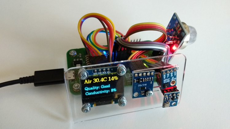
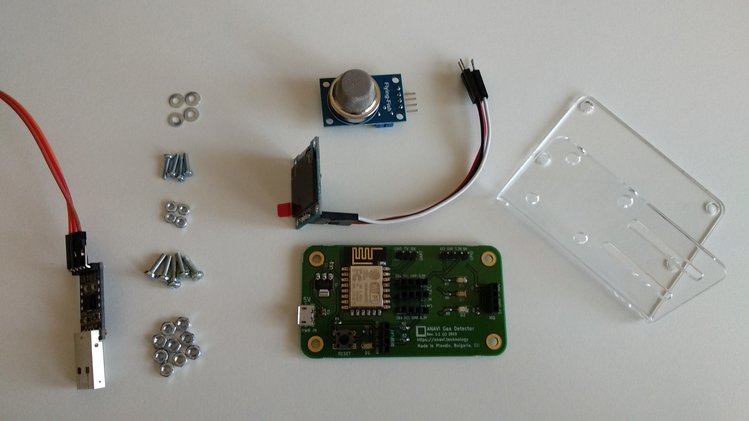
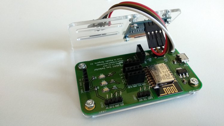
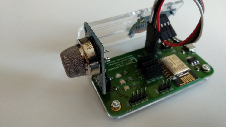
ANAVI Gas Detector is an ESP8266-powered, open source, Wi-Fi dev board for monitoring air quality and detecting dangerous gases. In the previous blog post I have shared the exact steps how to assemble it. Now I will cover the straight-forward process for connecting it to your Wi-Fi network. It is very simple and takes less than a couple of minutes.

Step 1: Turn on ANAVI Gas Detector

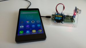
When you turn on ANAVI Gas Detector for the first time, it will create its own Wi-Fi Access Point with the name ANAVI Gas Detector followed by a unique five character ID.

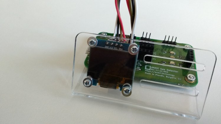
These characters are actually the end of the MD5 hash generated from the unique chip ID of the ESP8266 module. To avoid confusion, the same five characters are showed on the mini OLED display included in all kits of ANAVI Gas Detector.

Connect to the Wi-Fi access point created by ANAVI Gas Detector from your smartphone, tablet or personal computer.

Step 2: Captive Portal

Once you have connected to the Wi-Fi access point created by ANAVI Gas Detector, a captive portal will pop-up and guide you to the next steps. Click Configure WiFi as shown in the video.

Step 3: Configure

Select your local Wi-Fi network, enter a password (if it is not open), type in MQTT broker address, port, username and password.

By default, just for demo purposes, ANAVI Gas Detector connects to iot.eclipse.org with port 1883 and no username/password. This is a public MQTT broker just for demonstrations. It is highly recommended to install open source MQTT broker locally and connect ANAVI Gas Detector to it.

Optionally, you can also select a temperature scale. By default it is set to Celsius. Of course, Fahrenheit is also supported. To switch just type in fahrenheit.

Finally, when ready, just click Save. ANAVI Gas Detector will reboot and try to connect first to your Wi-Fi network and after that to the configured MQTT broker. If it experience problems connecting you will be asked to do the configuration again.

That’s it! The whole process requires just these three easy steps and takes less than a couple of minutes. No need to download & install any apps on your smartphone. If you don’t have a smartphone – you can do the configuration from your personal computer or a tablet.

One More Thing…

Once ANAVI Gas Detector is up and running, if you need to change the configurations, just press and hold the RESET button on the board for 10 seconds. Keep the RESET button pressed until the D1 indication LED on the board is blinking.

This way you will wipe out all configuration, reset ANAVI Gas Detector to factory default and you will be asked to connect it again to your Wi-Fi.

For more details please also read our update at Crowd Supply and watch the short video.

You may also like

ANAVI Gas Detector Assembly Guide

ANAVI Gas Detector is an ESP8266-powered, open source, Wi-Fi development board for monitoring air quality and detecting dangerous gases. After a very successful crowdfunding campaign at Crowd Supply we are manufacturing a batch of units in Plovdiv, Bulgaria. All kits of ANAVI Gas Detector also include MQ-135 sensor module, USB to UART debug cable, an acrylic stand and a mini OLED I2C display. In this article you will learn how to get started and assemble all parts in about 10 minutes.

The printed circuit board of ANAVI Gas Detector has the same dimensions as the one for my other open source product ANAVI Thermometer so actually both use the same laser cut acrylic stand. Both ANAVI Gas Detector and ANAVI Thermometer have been designed using the open source software KiCAD. The open source software OpenSCAD was used to design the case.

ANAVI Gas Detector Developer Kit

In this article you will learn the exact steps how to assembly ANAVI Gas Detector Starter Kit. The procedure is the pretty much the same for Advanced and Developer kits, however they including additional I2C sensor modules. Appropriate nuts, screws and washers are included in all kits.

Getting started with ANAVI Gas Detector Starter Kit

Step 1

Peel off the protective film from the acrylic stand. Also remove the protective film from the display.

Step 2

Mounting the mini OLED display to the acrylic stand

Using a screwdriver, gently attach the mini OLED display to the acrylic stand with the M2 screws and nuts as shown on the photo. The mini OLED display is fragile so please be very careful. Do NOT fasten it too tight because the torque may break it.

Step 3

Add four M2.5 screws and nuts to the case of the acrylic stand. In the next step we will put ANAVI Gas Detector on top of the nuts.

Step 4

Add ANAVI Gas Detector on top of the nuts and fasten it with the additional M2.5 nuts. At the end you will have a spare M2.5 screw and nut to optionally attach an additional sensor to the acrylic enclosure.

Step 5

Connect the mini I2c OLED display to the dedicated slot for it on ANAVI Gas Detector

Gently connect the mini OLED display to the dedicated slot using the male to female jumper wires. The colors of the wires do not matter. Just have a look at the labels on the top of the OLED display and connect each of the four pins to a pin with the same label on the dedicated slot for the display on ANAVI Gas Detector.

Add the MQ-135 sensor module for monitoring air quality

Plug the MQ-135 sensor module in slot labeled as MQ. Owners of Advanced or Developer kit should also plug the additional I2C sensor modules.

Finally, you are ready to turn on and enjoy ANAVI Gas Detector!

On first boot you need to calibrate MQ-135 and configure and connect ANAVI Gas Detector to your WiFi network.

The so called “burn-in” procedure for initial calibration of MQ-135 is important to be done on first boot. Despite its fancy name it is actually quite easy. Just place ANAVI Gas Detector with MQ-135 sensor module in a room with clean air and leave it running for at least 24 hours. This has to be done only once when MQ-135 sensor module is used for the first time. After doing this procedure, on every next boot ANAVI Gas Detector and MQ-135 will do a quick calibration in couple of minutes and start working properly.

We have also published this tutorial as an update at Crowd Supply to notify all backers of ANAVI Gas Detector. The whole user’s manual for ANAVI Gas Detector is available at GitHub. This is an entirely open source project so as usual ideas for improvements and bug fixes are always welcome!

You may also like

How to Use Mini Monochrome OLED I2C Displays (SSD1306)?

Mini monochrome OLED I2C displays are cheap, reliable and easy to use by makers. They come in a huge variety of sizes. Our open source hardware Internet of Things, like ANAVI Thermometer and ANAVI Gas Detector, support this type of display and all kits include a particular yellow-blue model that is a bit below 1”. The display has 4 mounting holes. The screen resolution is 128×64 pixels. The driver is SSD1306. You can find exactly the same type of display with only white OLED pixels. The usage is the same no matter what is the color of the OLED pixels.

ANAVI Thermomter with yellow-blue mini OLED I2C display

In this video tutorial you will learn the exact steps how to get started with I2C OLED mini display with about 1” diagonal on Arduino compatible board such as our ANAVI Thermometer. ANAVI Thermomter is an ESP8266-powered, open source, Wi-Fi dev board with temperature and humidity sensors.

Continue reading “How to Use Mini Monochrome OLED I2C Displays (SSD1306)?”

You may also like

How to Use MQ-135 Gas Sensor?

There is a huge variety on the market of analog MQ gas sensor modules for Arduino compatible devices. In this article we will focus on MQ-135.  This low-cost analog sensor is used in air quality control equipment for buildings and offices. It is suitable for detecting of NH3, NOx, alcohol, Benzene, smoke, CO2 and other dangerous gases.

Continue reading “How to Use MQ-135 Gas Sensor?”

You may also like