Esptool is a free and open source ESP8266 and ESP32 serial bootloader command-line utility. The source code is available at GitHub under GPLv2 license. It is written in Python therefore it is universal and runs on Microsoft Windows, Mac OS and any GNU/Linux distribution (Ubuntu, Debian, Linux Mint, Fedora, CentOS, OpenSUSE, etc).
Installation
As of today esptool works fine with Python 2.7 or Python 3. Python 2 has been deprecated since January 1, 2020 therefore it is recommended to use esptool with Python 3.
The easier way to install the latest stable version of esptool is from pypi via pip. Open a terminal and execute the following command:
pip install esptoolFlashing Firmware
Using write_flash argument esptool flashed pre-compiled binary to devices with ESP8266 or ESP32. Here are the exact steps:
- Download an appropriate binary for your ESP8266/ESP32 device.
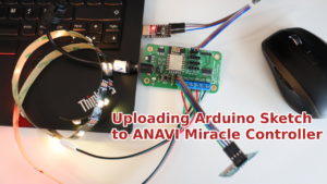
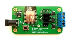
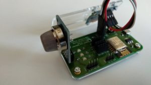
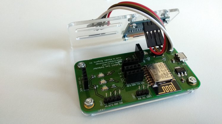
- Connect your device to a computer. For example, for ANAVI Thermometer, ANAVI Gas Detector, ANAVI Light Controller and ANAVI Miracle Controller you must use UART to USB debug cable.
- Turn on the device in boot mode. For example, on ANAVI Thermometer, ANAVI Gas Detector, ANAVI Light Controller and ANAVI Miracle Controller, press and hold the RESET button and plug the power supply.
- In a terminal execute the following command:
esptool.py --port /dev/ttyUSB0 --baud 460800 write_flash --flash_size=detect 0 firmware.bin Finding the Right Firmware
All ANAVI Internet of Things with ESP8266/ESP32 combine free and open source software with open source hardware. The firmware is built using Arduino IDE and a pre-compiled binary file is available at GitHub. Follow the links below to identify your ANAVI device and download appropriate binary for the latest stable firmware:
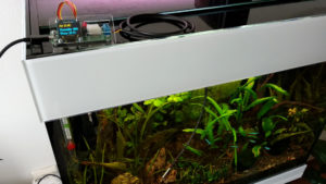
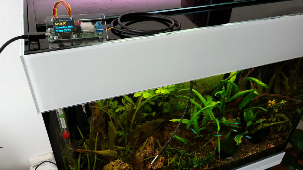
- ANAVI Thermometer
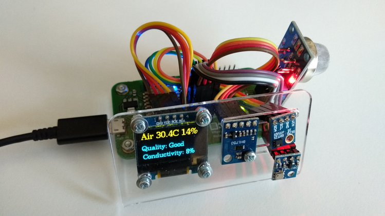
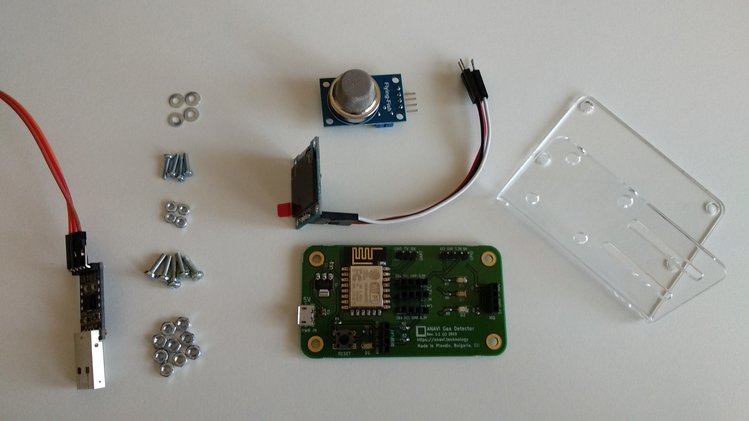
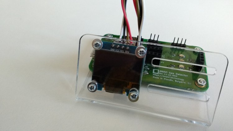
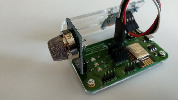
- ANAVI Gas Detector
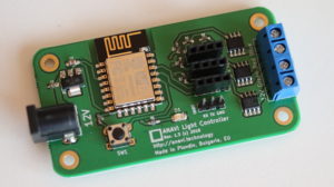
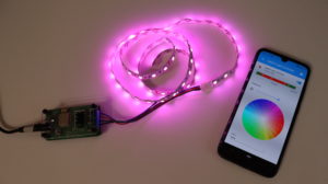
- ANAVI Light Controller
- ANAVI Miracle Controller
- ANAVI Fume Extractor
Of course, alternatively, instead of using esptool you can build the firmware from source through Arduino IDE or PlatformIO.