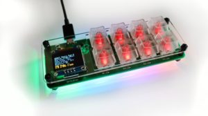
In a previous update we shared the exact steps how to assemble ANAVI Macro Pad 8 Developer Kit. Now let’s have a look at the Maker Kit.
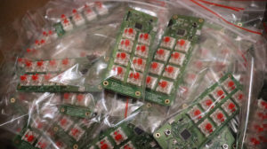
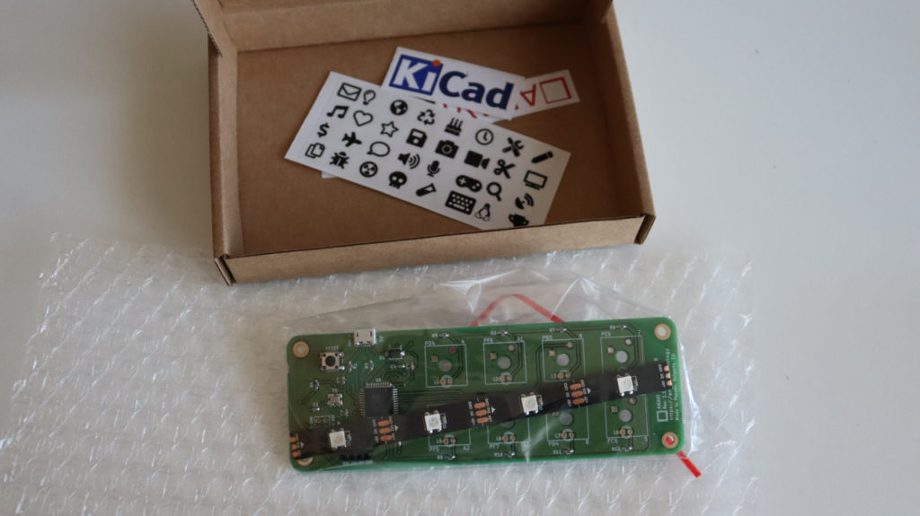
The maker kit provides the printed circuit board (PCB) and an addressable LED strip. There are also some nice stickers. Other accessories have to be purchased separately. You can use any mechanical switches compatible with Cherry MX plate footprint and 3mm LEDs.
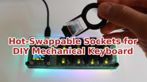
Furthermore with the maker kit you can perform a hot-swap upgrade of ANAVI Macro 8. It requires a very specific procedure which was explained in a previous article. If you have this in mind don’t solder anything and have a look at the other video tutorial.
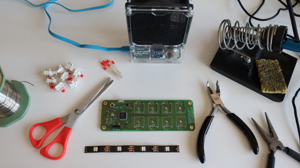
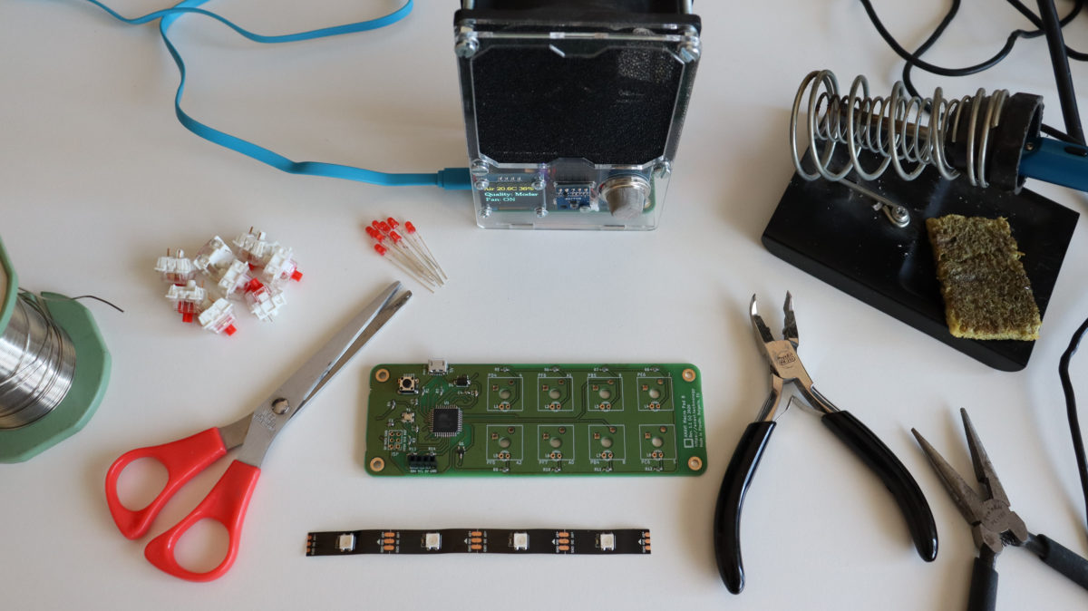
The assembly of ANAVI Macro Pad 8 Maker Kit requires soldering and advanced skills. The following tools are required:
- Soldering iron
- Scissors
- Optionally: screwdriver, tweezers and a keycap puller
It is also a good idea to stay safe and get a smoke absorber while soldering, for example our open source ANAVI Fume Extractor.
Please have a look at the video and follow the steps below if you have ANAVI Macro Pad 8 Maker Kit.
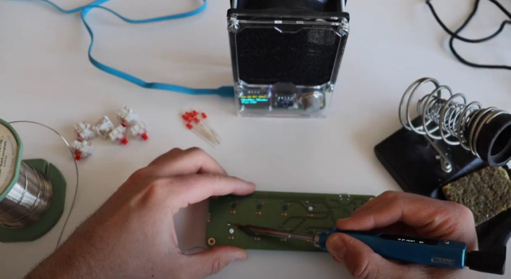
Solder mechanical switches to the PCB
Any type of mechanical switch compatible with Cherry MX plate footprint is suitable for ANAVI Macro Pad 8. The developer kit comes with Gateron mechanical switches. The maker kit allow you to use different brand and color.
Choosing the most appropriate switch for your needs and taste is a matter of personal preference. There are many different brands and colors. For example, the blue mechanical switches are more noisy which could be sometimes fun but also annoying during daily work. The red switches are fast and not very noisy therefore they are often proffered by gamers.
There are two pins on each mechanical switch that must be soldered to the printed circuit board. That makes 16 pins in total. The position of the each pin is very specific and the switch goes into the PCB. One of the pins is for the signal coming from the Microchip ATmega32U4 microcontroller, the other pin is for ground.
Solder 3mm LED
This step is actually optional depending on the the type of the mechanical switch. Some mechanical switches may not have a hole in the plastic enclosure for a 3mm LED.
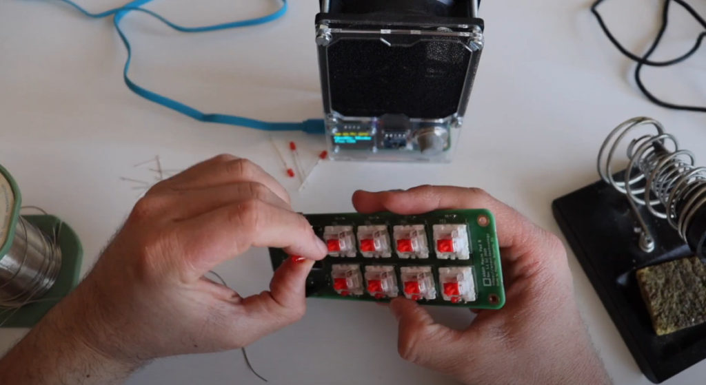
Each 3mm LED for through-hole soldering has 2 legs. The longer leg is the positive terminal, also known as anode. The shorter leg is negative and also known as cathode.
The shorter leg that indicates the negative terminal must go into the square hole of the PCB. ANAVI Macro Pad 8 has 8 mechanical switches therefore 8 LEDs are required. If you want you can use different color of the LEDs. You can even mix colors.
Solder WS2812B addressable LED strip to the back of the PCB
Using scissors cut a little bit from both ends of the LED strip to make sure it will stretched when placed on the board. However it is tricky, be careful and make sure enough from the pads are available to make a good contact after soldering them.
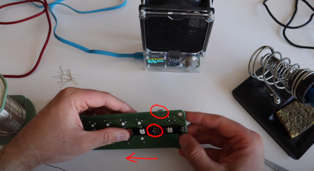
It is very important to properly set the direction of the WS2812B LED strip. On the LED strip you will notice small arrows indicating the direction. They should point from the microUSB connector towards the other end of the PCB as shown in the video.
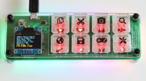
If you have successfully completed these 3 steps your ANAVI Macro Pad 8 should look just like a developer kit having all accessories soldered. Therefore the next steps are the same as for both the developer and the maker kit. Explore them at our previous blog post as well as in the user’s manual.
Thank you for using ANAVI Macro Pad 8 and for supporting this entirely open source project!