Getting Started with the open source JavaScript Internet of Things platform ioBroker

ioBroker is an open source Internet of Things platform written in JavaScript and using Node.js for the back-end. It is perfect to run on single board computers such as Raspberry Pi. The project started in 2014. The source code is hosted in GitHub and the core is available under MIT license. The creators and maintainers of ioBroker are from Germany and the project is very popular among the German open source community interested in home automation.

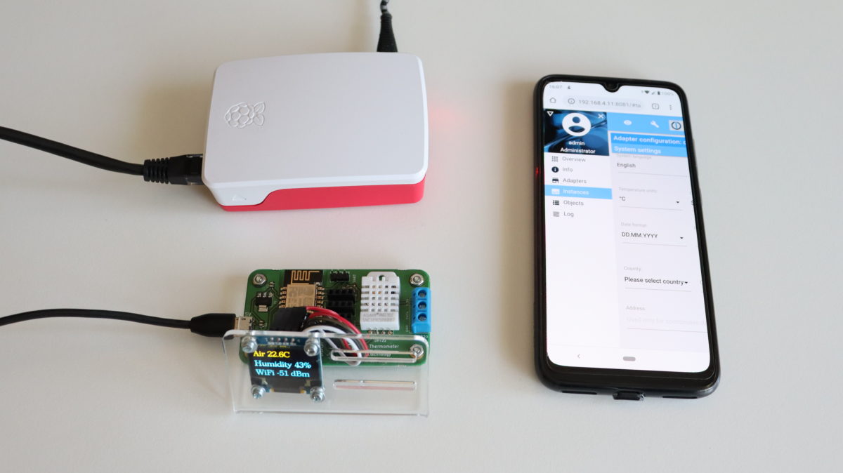
In this article you will learn how to get started with ioBroker by installing it on a Raspberry Pi and after that how to measure temperature and humidity from the built-in DHT22 sensor on ANAVI Thermometer through the machine-to-machine protocol MQTT.

ioBroker Installation Guide

Step by step video tutorial for installing ioBroker on Raspberry Pi

Only two steps are required to install ioBroker on GNU/Linux distributions, including on a Raspberry Pi with Raspbian:

curl -sL https://deb.nodesource.com/setup_10.x | sudo -E bash -
sudo apt-get install -y nodejs
curl -sL https://iobroker.net/install.sh | bash -

After successfully installing ioBroker, open the web interface and complete the initial setup as explained in the video.

Monitoring Temperature and Humidity from DHT22 in ioBroker via MQTT

Integrating ANAVI Thermometer with DHT22 temperature and humidity sensor in ioBroker

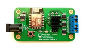
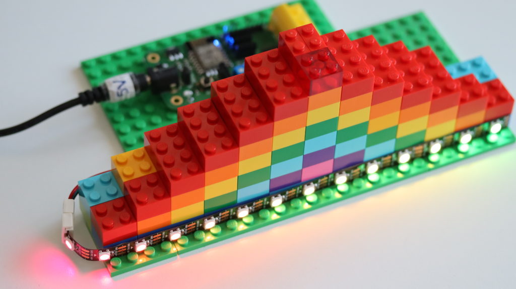
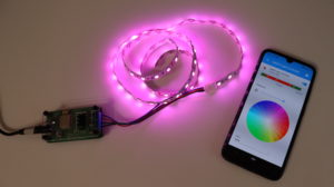
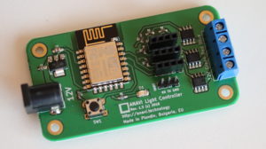
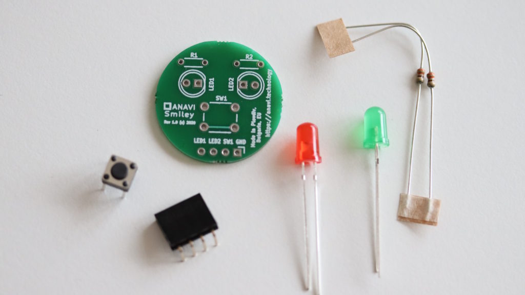
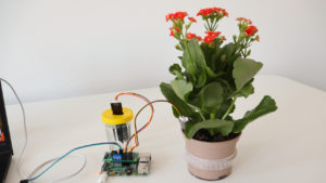
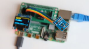
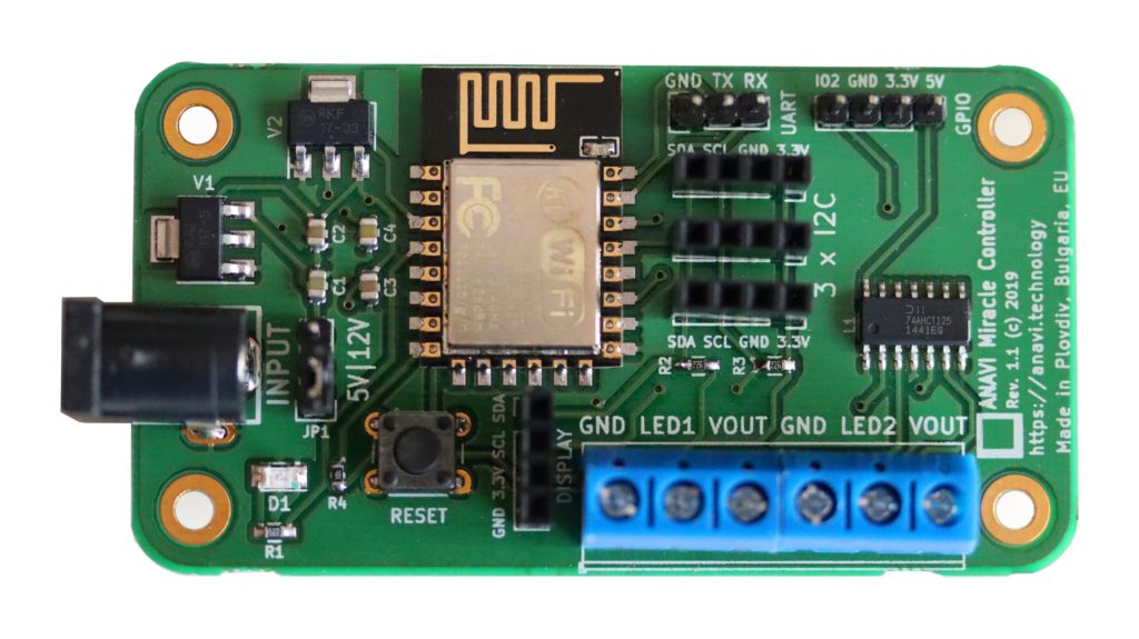
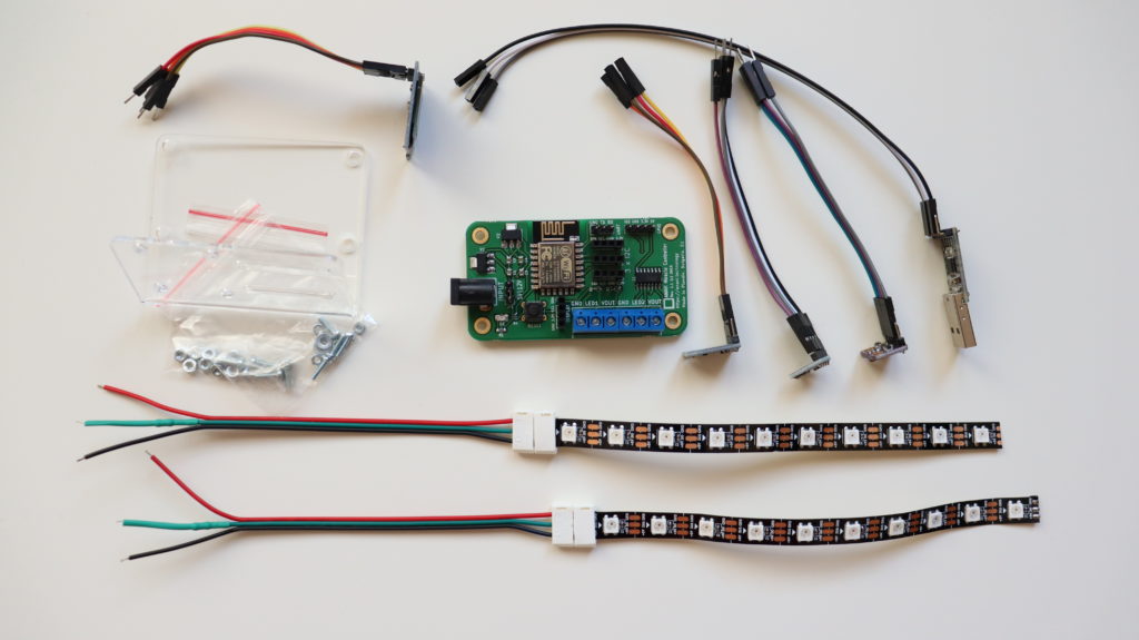
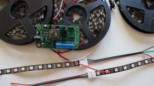
ANAVI Thermometer is an open source hardware, Wi-Fi development board for measuring temperature that’s powered by an ESP8266 processor. It comes with a built-in DHT22/AM2302 temperature and humidity sensor and has slots for a mini OLED display, waterproof DS18B20 temperature sensor, and empty slots for up to three additional I2C sensor modules.  Out of the box, the open source firmware of ANAVI Thermometer, works with Home Assistant specification for automatic discovery and MQTT messages with JSON payload.

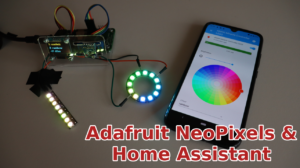
Although ioBroker is an alternative open source IoT platform, through an adapter it supports the Home Assistant specification. The process for using ANAVI Thermometer in ioBroker is straight-forward thanks to the adapters MQTT Client/Broker and HASS-MQTT.

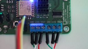
Adapter MQTT Client/Broker can be configured either as MQTT broker or as a client mode and use an external broker. In the particular demonstration in the video the instance of ioBroker adapter MQTT Client/Broker has been configured as a broker, without username/password and with disabled publish check-boxes from the MQTT Settings tab.

Adapter HASS-MQTT is required to support the Home Assistant MQTT specification. It have to be installed separately and bound to the instance of adapter MQTT Client/Broker as shown in the video. Get the HASS-MQTT adapter from: https://github.com/smarthomefans/ioBroker.hass-mqtt

ANAVI Themometer reporting temperature and humidity to the open source IoT JavaScript platform ioBroker

After turning on the instances of both adapters in Home Assistant, ANAVI Thermometer must be configured to connect to the same MQTT broker. After that ANAVI Thermometer will be automatically detected and the data from DHT22 as well as from any other attached supported sensors will be automatically reported to ioBroker. You just need to configure how to display it in your preferred graphical user interface (ioBroker offers several of them). In the video I used the ioBroker visualisation adapter which requires activation through an unique key. The activation requires registration with a email and is not shown in the video. Adapter visualisation if free for personal use. The other adapters, MQTT Client/Broker and HASS-MQTT are free and open source without any limitations.

You may also like

Let’s Build Together smart LEGO Rainbow with Home Assistant

Recently the famous toy manufacturer LEGO announced a competition to build a rainbow as a symbol of hope. Although the challenge is targeted primary for kids, there are no age restrictions so veterans can also join.

#LetsBuildTogether ​a smart LEGO rainbow with WS2812B LED strip and control it from Home Assistant

This was a great opportunity to have some fun and to add an addressable LED strip which through ANAVI Miracle Controller can be controlled remotely via web interface or moble application of the popular open source home automation platform Home Assistant.

Front view of the LEGO rainbow with a WS2812B LED strip on the first row

To build something similar you will need:

A LEGO rainbow shining at night thanks to ANAVI Miracle Controller and WS2812B LED strip

Although ANAVI Miracle Controller supports 2 addressable LED strips, for this particular use case only one is used so during the initial configuration set the number of LEDs of the other LED strip to 0. This way only one LED strip will be automatically discovered by Home Assistant over the machine to machine protocol MQTT.

A look of our LEGO rainbow from the top

For more details how to enable Home Assistant discovery over MQTT have a look at our other step by step video tutorials for assembly guide, WS2811 12V LEDs as well as for NeoPixels.

You may also like

Getting Started with esptool for flashing firmware on ESP8266 and ESP32

Esptool is a free and open source ESP8266 and ESP32 serial bootloader command-line utility. The source code is available at GitHub under GPLv2 license. It is written in Python therefore it is universal and runs on Microsoft Windows, Mac OS and any GNU/Linux distribution (Ubuntu, Debian, Linux Mint, Fedora, CentOS, OpenSUSE, etc).

Installation

As of today esptool works fine with Python 2.7 or Python 3. Python 2 has been deprecated since January 1, 2020 therefore it is recommended to use esptool with Python 3.

The easier way to install the latest stable version of esptool is from pypi via pip. Open a terminal and execute the following command:

pip install esptool

Flashing Firmware

Using write_flash argument esptool flashed pre-compiled binary to devices with ESP8266 or ESP32. Here are the exact steps:

  • Download an appropriate binary for your ESP8266/ESP32 device.
  • Connect your device to a computer. For example, for ANAVI Thermometer, ANAVI Gas Detector, ANAVI Light Controller and ANAVI Miracle Controller you must use UART to USB debug cable.
  • Turn on the device in boot mode. For example, on ANAVI Thermometer, ANAVI Gas Detector, ANAVI Light Controller and ANAVI Miracle Controller, press and hold the RESET button and plug the power supply.
  • In a terminal execute the following command:
esptool.py --port /dev/ttyUSB0 --baud 460800 write_flash --flash_size=detect 0 firmware.bin 

Finding the Right Firmware

All ANAVI Internet of Things with ESP8266/ESP32 combine free and open source software with open source hardware. The firmware is built using Arduino IDE and a pre-compiled binary file is available at GitHub. Follow the links below to identify your ANAVI device and download appropriate binary for the latest stable firmware:

Of course, alternatively, instead of using esptool you can build the firmware from source through Arduino IDE or PlatformIO.

You may also like

ANAVI Smiley Add-on Board for Raspberry Pi

ANAVI Smiley is a simple open source hardware add-on board for Raspberry Pi. It is compatible with any Raspberry Pi model or version. ANAVI Smiley has educational purposes: it is useful for learning how to solder and how to program. The simplicity of the board makes the kit appropriate for beginner. Example application written in Python shows how to use it.

Closer look at ANAVI Smiley after soldering the kit

ANAVI Smiley combines open source hardware with free and open source software. It has been certified by the Open Source Hardware Association under UID BG000061. ANAVI Smiley is available as a soldering kit with through-hole components:

  • Printed Circuit Board (PCB)
  • 2 LEDs
  • 2 resistors
  • Tactile button
  • Female connector
ANAVI Smiley soldering kit with all components

The color of the LEDs may vary. The primary kit includes with one green and another red LED, but there is also a kit with 2 yellow LEDs.

ANAVI Smiley with red and green LED as well another unit with 2 yellow LEDs

Have a look at the video for the exact steps how to solder ANAVI Smiley and to use it with Raspberry Pi.

A photo of ANAVI Smiley a moment after the kit has been assembled.

The short leg of the LED must go to ground (GND), aka the hole marked with a square on the printed circuit board. It is recommended to solder 4-pin connector on the opposite side, as shown on the picture. This way ANAVI Smiley will fit better on the 40-pin header of Raspberry Pi.

Python3 script to use ANAVI Smiley on a Raspberry Pi is available at GitHub. It relies on gpiozero to control the LEDs and to read the state of the button. Gpiozero is a simple and convenient Python interface to GPIO devices with Raspberry Pi, started by Ben Nuttall and Dave Jones.

Please note that SW1 button on the PCB doesn’t have a resistor, therefore your application must use the internal pull-up resistor present on each Raspberry Pi GPIO, for example with gpiozero in Python and pin 26:

btn = Button(26, pull_up = True, bounce_time=0.1)
ANAVI Smiley PCB in KiCad

ANAVI Smiley has been designed with the free and open source software tool KiCad. The whole KiCad project is also in GitHub. The two layer printed circuit board is made in Plovdiv, Bulgaria.

You may also like

Plovdiv – European Capital of Open Source Hardware!

OSHdata is a brand new independent project launched in 2020. The goal is to report the state of the Open Source Hardware (OSH) based on the data from the certification program of Open Source Hardware Association. Recently OSHdata announced a public report for 2020.

All time open source hardware frequent creators as of February 2020

ANAVI Technology made it to 7th place in the hall of fame for OSH Frequent Certification Creators! Absolute number 1 are our neightbours Olimex. We are all from Plovdiv, Bulgaria and this is not just a coincidence!

Olimex is specialized in open source hardware. They are open source hardware pioneers and have hundreds of open source products. The company was established in 1991 in Plovdiv, Bulgaria. Olimex development boards and derivatives based on them are used in numerous industrial applications around the world: agricultural tractors, 3D printers, huge mining machines, smart traffic lights, variable speed drivers for oil, gas pumps and conveyors, etc. If you are curious to learn more have a look at Tsevan Uzunov’s (CEO of OLimex) talk at FOSDEM 2020.

Several years ago Olimex decided to switch from EAGLE to KiCad for designing their printed circuit boards. They designed complicated devices with multi-layer boards using KiCad like the do-it-yourself laptop Olimex Teres-I and A64-OLinuXino embedded Linux computer. FreedomBox Foundation even relies on Olimex for Pioneer-FreedomBox-HSK!

After switching to KiCad, engineers from Olimex made numerous free workshop to share their experience. KiCad is a free and open source Electronic Design Automation (EDA) tool that runs on MS Windows, Mac OS and GNU/Linux distributions.

Is there any point to make open source hardware with proprietary tools? Not at all! This is why KiCad is a great open source tool for making open source hardware. Back in the days, ANAVI Technology was started and adopted KiCad entirely because of all the knowledge shared by Olimex.

Considering the total number of certified products by Olimex and ANAVI Technology, Bulgaria is the leading country in Europe and obviously Plovdiv is European capital of open source hardware!

Since March 2018, following the recommendations of Drew Fustini, all products of ANAVI Technology are certified by the Open Source Hardware Association (OSHWA).

One more thing: Olimex, Drew, thank you 🙂

You may also like

Holiday Lights with Home Assistant, ANAVI Miracle Controller, and Olimex WS2811 LED Ropes

This YouTube video demonstrates do-it-yourself (DIY) holiday lights to celebrate Christmas or Halloween using ANAVI Miracle Controller, Olimex WS2811 LED ropes and the popular open source home automation platform Home Assistant!

ANAVI Miracle Controller and Olimex LED-Ropes-10 managed from Home Assistant app for Android

All kits of ANAVI Miracle Controller come with WS2812B LED strip, however the board is also compatible with other addressable LED strips. In a previous update we covered Adafruit NeoPixels and now we are focussed on Olimex WS2811 LED Rope.

ANAVI Miracle Controller with mini OLED display and a couple of Olimex LED-ROPE-10

Required Hardware

  • ANAVI Miracle Controller
  • 5V power supply
  • Two Olimex LED-ROPE-10
  • Raspberry Pi (recommended 3 or newer) with Home Assistant

Olimex is a well-known company in the maker community and I am lucky because their headquarter is my hometown Plovdiv, Bulgaria.

Olimex offers addressable, water proof, sealed with resin RGB WS2811 ropes with various number of LEDs. For this video I used a couple of Olimex LED-ROPE-10. The rope is waterproof so it is suitable for both indoor and outdoor installations. It works with power supply in the range from 3.3V to 5.5V and has a dedicated WS2811 driver for each LED.

The typical color code for Olimex LED-ROPE-10:

  • Olimex rope RED wire – VCC (3.3V-5.5V)
  • Olimex rope GREEN/BLUE (varies) wire – GND
  • Olimex rope WHITE wire – DATA

Each RGB LED in Olimex rope draws approximately 50mA at 5V with red, green, and blue at full brightness. Olimex LED-ROPE-10 has only 10 RGB LEDs with makes approximately 500mA and it is OK to power it through ANAVI Miracle Controller. For installation will longer ropes with bigger consumption wire the VCC and GND lines directly to the power supply.

When using Olimex LED ropes, set ANAVI Miracle Controller to 5V input and use an appropriate 5V center positive power supply!

For Olimex LED-Ropes-10 set ANAVI Miracle Controller to 5V and use appropriate 5V power supply
Wiring of a couple of Olimex LED-ROPE-10 to ANAVI Miracle Controller

NOTE: The color codes of other addressable LED strips, including WS2812B LED strip from all kits, are different!

Due to differences in color codes this wiring is valid only for Olimex LED ropes. Be careful and check the proper wiring as well input voltage requirements if you are using a different type of addressable LED strip or rope.

Software

Home Assistant must be installed on an appropriate device. If you haven’t installed it already, a single board computer like Raspberry Pi (version 3 or newer) is the perfect fit!

MQTT broker is also required and must be installed. You can install Mosquitto from Home Assistant add-on store. Integrate the MQTT broker in Home Assistant and enable discovery. The exact steps have been covered in a previous blog post about ANAVI Miracle Controller and Adafruit NeoPixels.

Please, ensure you are running the latest version of the open source firmware for ANAVI Miracle Controller. It is available at GitHub. You can flash it through Arduino IDE following these steps.

After completing the initial installation and integration in Home Assistant, you can easily control the holiday lights from your personal computer, smartphone or tablet. You can either install the official mobile app on your smartphone or use the web interface from any modern HTML5 web browser (Google Chrome, Mozilla Firefox, etc). Furthermore, with Home Assistant you can create automation and trigger automatically the holiday lights depending on various events.

You may also like

ANAVI Fume Extractor Is Coming Soon…

Stay safe while soldering with ANAVI Fume Extractor

ANAVI Fume Extractor is an entirely open source smart solder smoke absorber certified by the Open Source Hardware Association (OSHWA) with UID  BG000060. ANAVI Fume Extractor is powered by a Wi-Fi development board with ESP8266, 80mm fan and a replaceable carbon filter. It has a dedicated slots for a mini OLED I²C display and MQ-135 gas sensor module as well as slots up to 3 additional I²C sensor modules. Furthermore, there are UART pins for easy flashing of custom software and an extra GPIO for connecting external peripherals.

ANAVI Fume Extractor

We are preparing a crowdfunding campaign to support low-volume manufacturing in Plovdiv, Bulgaria. Learn more about ANAVI Fume Extractor and subscribe for updates at Crowd Supply.

You may also like

ANAVI Smiley and ANAVI Tag Manager Certified by the Open Source Hardware Association

The primary goal of ANAVI Technology Ltd. is to combine open source hardware with free and open source software. So far numerous of our development boards have been certified by the Open Source Hardware Association (OSHWA). In February 2020 a couple new products were also certified: ANAVI Smiley and ANAVI Tag Manager. Both of them have been designed with the free and open source tool KiCad.

A lot of products on the market claim their are open source hardware, however this is not always true. Open Source Hardware certification allows the community to quickly identify hardware that truly complies with the definition of open source hardware. Because of this certification by OSHWA is important for us.

ANAVI Smiley

Image
ANAVI Smiley add-on board for Raspberry Pi as a soldering kit

ANAVI Smiley is a simple add on for Raspberry Pi that comes as a soldering kit. It has a couple of LEDs and a button. A simple Python 3 application for using this add-on board is available at GitHub. ANAVI Smiley was certified by OSHWA with UID BG000061. It has been designed as a prize for the teams competing at Pi Wars 2020. Soon ANAVI Smiley will be also available on sale at tindie.

ANAVI Tag Manager

Image
ANAVI Tag Manager with PN532 NFC RFID module and an acrylic enclosure

ANAVI Tag Manager is a WiFi development board for using PN532 NFC RFID module. The board is using ESP8266. It is powered from microUSB connector. There are slots for UART pins, mini OLED display and up to 3 I2C sensor modules. Furthermore there is also an extra GPIO pin for custom automation solutions. ANAVI Tag Manager is useful for various applications with NFC, including smart locks and payment systems. It has been certified by OSHWA with UID BG000062.

Stay tuned for new articles with details about both of these exciting new open source hardware gadgets!

You may also like

HackSpace Magazine Covered ANAVI Miracle Controller

HackSpace is a monthly magazine for makers. We are very proud that issue 27 for February 2020 covered our open source hardware ANAVI Miracle Controller in section “Crowdfunding now”. You can buy HackSpace issue 27 or download it as a PDF for free.

ANAVI Miracle Controller is an open source hardware development board for simultaneously managing a couple of 5V or 12V addressable (digital) LED strips. Furthermore you can attach to it mini OLED display and up to 3 I2C sensor modules. The default firmware is available as an Arduino sketch at GitHub. Out of the box it is compatible with the popular open source automation software Home Assistant over the machine-to-machine protocol MQTT.

Right now we are running a crowding campaign at Crowd Supply to fund mass manufacturing of ANAVI Miracle Controller.  We hope you’ll jump in and help us develop further this entirely open source project!

You may also like

Flashing Firmware on ANAVI Miracle Controller with Arduino IDE

ANAVI Miracle Controller is a new entirely open source development board for addressable (digital) LED strips like NeoPixels, WS2812B, WS2811, etc. The major advantages are that you can control two LED strips simultaneously, add a mini OLED display and I2C sensor modules as peripherals. Recently we launched a crowdfunding campaign for it at Crowd Supply.

ANAVI Miracle Controller

ANAVI Miracle Controller is a development board and it is easy to flash a custom firmware on it. The process is very similar as for our other open source project like ANAVI Thermometer, ANAVI Gas Detector and ANAVI Light Controller.

This tutorial explains the exact steps how to compile and upload the default open source Arduino sketch for ANAVI Miracle Controller using Arduino IDE.

Required Hardware

  • ANAVI Miracle Controller
  • USB to UART debug cable
  • Addressable LED strip
  • Appropriate power supply at 5V or 12V depending on the type of LED strips
  • Personal computer with MS Widows, Mac OS or GNU/Linux distribution
  • Optionally a mini OLED display and other peripherals can be attached
ANAVI Miracle Developer kit

Download Source Code from GitHub

The default firmware of ANAVI Miracle Controller is an open source Arduino sketch. It relies on several popular open source Arduino libraries, including FastLED for controlling addressable LED strips. Clone or download the source code from GitHub.

Connecting UART to USB

Each ANAVI Miracle Controller kit includes a USB to UART debug cable with CP2102. Depending on the operating system on your PC you might be required to install additional drives. It works out of the box on GNU/Linux distributions. As open source enthusiasts we are using it on Ubuntu. Plug the USB in your computer and connect the 3 wires as follows:

ANAVI Miracle ControllerUSB to UART Debug Cable
RXTX
TXRX
GNDGND
Connecting USB to UART cable to ANAVI Miracle Controller

Download Arduino IDE

Download and install Arduino IDE on your personal computer. It is free and open source software available for MS Windows, Mac OS and GNU/Linux distributions.

Launch Arduino IDE. From File > Open load an Arduino sketch. It can be the default firmware or any other compatible with ANAVI Miracle Controller Arduino sketch.

Configure ESP8266 in Arduino IDE

Go to File > Preferences. Select Settings and in the field Additional Boards Manager URLs add: http://arduino.esp8266.com/stable/package_esp8266com_index.json

From Arduino IDE select Tools > Board: Generic ESP8266 Module. Set the flash size to 4M (1M SPIFFS). The upload speed is 115200. Adjust the exact port of USB to serial debug cable connected to your computer.

Install Libraries

Select Tools > Manage Libraries. The Arduino library manager will appear. Install all required libraries and their exact versions. Over the time, with the development of the default firmware, new libraries might be added. Please have a look at the README file to get the up to date list of all Arduino libraries on which the the default firmware depends on.

Compile & Upload

In Arduino IDE click Verify/Compile. If there are any errors, please double check that you have installed all required libraries and their exact versions. If the source code compiles successfully, please proceed to to the next step for flashing the firmware.

Set the jumper to 5V or 12V depending on the type of addressable LED strip and power supply. Mismatch of the voltage may lead to severe hardware failure.

In Arduino IDE click Upload. Set the jumper on ANAVI Miracle Controller to 5V or 12V depending on your power supply and type of LED strips. The power supply voltage must match the required voltage by the LED strips, for example 5V for NeoPixels and the WS2812B included in all kits. Press and hold the RESET button on ANAVI Miracle Controller. Without releasing the RESET button, plug the power supply in the barrel jack of ANAVI Miracle Controller.

Do NOT release the RESET button until you see in Arduino IDE that the upload is 100% completed!

ANAVI Miracle Controller with 2 WS2812B LED strips connected to a laptop using USB to UART cable

You may also like