ANAVI Fume Extractor Assembly Guide

ANAVI Fume Extractor is an  open source smart solder smoke absorber useful for makers during soldering. It comes as a do-it-yourself kit. There are 3 types of kits with different sensor modules. ANAVI Fume Extractor is available at Crowd Supply, Mouser and Tindie.

ANAVI Fume Extractor video assembly guidelines

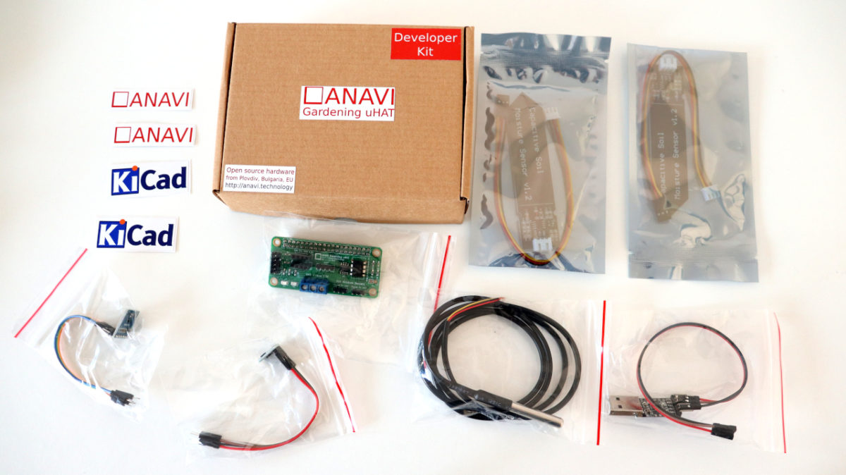
This tutorial explains the exact steps of how to assemble the ANAVI Fume Extractor developer kit which contains all supported peripherals. The whole process can take up to 30-40min. A screwdriver is required. It is highly recommended to watch the video with the assembly guidelines before you start.

Step 1: Peel off the protective films

Each ANAVI Fume Extractor kit contains 4 acrylic enclosures. Peel off the protective films from both sides of all of them. The acrylic enclosure will be clear and transparent once the film is peeled off.

Step 2: PCB

Attach the ANAVI Fume Extractor printed circuit board to the bottom acrylic enclosure with 4 screws and 8 nuts. Add 4 nuts below and 4 nuts above the board.

Step 3: Mini OLED Display

The kit includes 4 M2 screws and nuts as well as appropriate washers. Remove the protective film from the mini I2C OLED display. Carefully attach the display to the front acrylic case as shown in the video. The display is fragile. Don’t fasten the screws too tight!

Step 4: Fan Filter

A couple of fan filters are included in each kit. Attach the 4 M4 screws to the front acrylic enclosure with 4 of the M4 nuts. Place one of the filters. Leave the other one as a replacement.

For long-term maintenance over time the filter must be regularly replaced. There is a huge variety of 80mm fan filters on the market. It is up to you to decide whether to buy carbon or HEPA filters. Various distributors offer appropriate filters, for example Mouser has 80 mm, 45 PPI foam media filters.

Step 5: Fan

Add the acrylic enclosure that separates the fan from the filter. On the side of the fan you will notice a label that indicates the direction of the air flow. Place the 80mm 5V DC fan so that the air will flow through the filter.

Screw the 4 M4 20mm stand-offs to firmly fix the position of the fan.

Step 6 (optional): Light Sensor Module

Owners of a developer kit should add the BH1750 light sensor module to the front acrylic enclosure and fix it with one M4 screw and a nut.

Step 7: Peripherals

Connect peripherals, like the fan and the mini OLED display, to the printed circuit board. There are dedicated connectors for both of them. Pay attention to the labels for I2C on the top of the mini OLED display.

Step 8 (optional): Sensors

Owners of advanced or developer kits should attach:

  • MQ-135 for indoor air quality
  • HTU21D I2C sensor module for temperature and humidity
  • BMP180 I2C sensor module for barometric pressure and temperature.

Step 9: Assemble all acrylic enclosures

Finally, assemble together all acrylic enclosures by fastening 4 M4 nuts on the back of ANAVI Fume Extractor.

On the right side of ANAVI Fume Extractor you will notice a jumper for the WiFi as well as a button to switch the filter on and off. By default the jumper for the WiFi is set to OFF. Move it to ON and power cycle the board if you want to connect ANAVI Fume Extractor to a MQTT broker and IoT platform such as the popular open source system Home Assistant.

To turn ANAVI Fume Extractor on, gently plug an appropriate cable and 5V power supply into the microUSB connector on the left side of the board. The microUSB connector is used only for providing power, no data is transferred. Power supply and microUSB cable are NOT included in any of the kits.

For advanced or developer kits, on the first boot, it is very important to do what is called the “burn-in” procedure for initial calibration of MQ-135 air quality sensor module:

  • Place ANAVI Fume Extractor with the attached MQ-135 in a room with clean air
  • Leave it running for at least 24 hours

This has to be done only once when the MQ-135 sensor module is used for the first time. After doing this procedure, on every next boot ANAVI Fume Extractor and MQ-135 will do a quick calibration in a couple of minutes and start working properly.

MicroPython on Raspberry Pi Pico with Thonny IDE

Raspberry Pi Pico is a tiny and fast development board by the Raspberry Pi Foundation built using the brand new RP2040 32-bit dual ARM Cortex-M0+ microcontroller. The major advantage of Raspberry Pi Pico is the affordable price as it is available for about $4 (without taxes and shipping).

In this video tutorial you will learn how to get started with MicroPython using the open source Thonny IDE on Raspberry Pi Pico. Thonny runs on Mac, Windows and Linux distributions, in the video it is used on Ubuntu. The video includes Pico unboxing, MicroPython installation guide, blinking LED example, MicroPython REPL demo and conclusions.

Useful links:

The video tutorial was sponsored by PCBway which provide high-quality prototyping services. On the photo you can see prototypes of green printed circuit boards with white silkscreen following Raspberry Pi specifications for micro Hardware Attached on Top (uHAT).

ANAVI Gardening uHAT is now OSHWA certified

A few days ago we received an official confirmation that ANAVI Gardening uHAT has been certified as open source hardware by the Open Source Hardware Association with UID BG000079.

The Open Source Hardware Association (OSHWA) is a non-profit organization that supports the open source movement and maintains an open source hardware certification registry. OSHWA Certification provides an easy and straight-forward way to quickly check if a product complies with a uniform and well-defined standard for open source hardware.

Open source hardware certification guarantees the sharing of knowledge and keeps prices fairly based on the bill of materials of the hardware’s components. ANAVI Gardening uHAT hardware design files are available under CC BY-SA 4.0, which allows you to remix, transform, and build upon the material for any purpose, even commercially.

In a nutshell, OSHWA certifies a project as open source based on public access to four elements:

  • Hardware – functional elements of the product
  • Software – code, firmware, or other software involved in the product’s functionality
  • Documentation – including design files, schematics, and instructions
  • Branding – brand names, product names, logos, and product design

The exact certified version of each product receives a unique UID, for example, ANAVI Gardening uHAT is with UID BG000079. The prefix is the country code. We make our open source hardware in Plovdiv, Bulgaria, so the country code is BG. The suffix is a sequential ID number. At the moment, there are 79 certified open source hardware products from Bulgaria. For a comparison, the United States is leading with the amazing 2052 certified products, followed by Germany with 116. Bulgaria comes in at the third place, primarily thanks to our awesome open source neighbors from Olimex.

As a very small company we are all proud to have contributed to the Bulgarian success in this field. Hopefully, the popularity of the open source hardware movement will continue to increase worldwide.

ANAVI Gardening uHAT

ANAVI Gardening uHAT is a low-cost, open source Raspberry Pi add-on board that helps you develop smart solutions for monitoring and growing plants.

ANAVI Gardening uHAT supports multiple sensors for soil moisture, temperature, humidity, barometric pressure, and light. Getting started is easy: just plug it into a Raspberry Pi with your bare hands and follow the instructions in the user manual. No soldering is necessary, and no tools are required.

We hope you’ll jump in and help us bring this entirely open source gardening project to life by supporting our new crowdfunding campaign at Crowd Supply.

ANAVI Macro Pad 2 Developer Kit Assembly Guide

ANAVI Macro Pad is an open source, programmable two-key mechanical keyboard with backlighting. It was funded through a crowdfunding campaign at Crowd Supply.

ANAVI Macro Pad 2 Developer Kit does not require soldering. The assembly is easy, please take a look at the assembly video above for details. Although you can complete assembly with your bare hands, you might find a screwdriver and tweezers helpful.

ANAVI Macro Pad 2 Developer Kit includes a fully-soldered gold-plated green printed circuit board with two Gateron red mechanical switches, red 3 mm LEDs, an acrylic enclosure in two parts, two translucent keycaps, M2.5 screws, washers, and nuts, and awesome stickers!

To assemble ANAVI Macro Pad 2 follow these steps as shown in the video:

  • Peel off the protective films from both sides of the acrylic enclosure parts.
  • Assemble the top acrylic enclosure using two longer screws. It is not symmetric, so please pay attention to the position of capacitor C1.
  • Assemble the bottom acrylic enclosure using six nuts, three washers, and the shorter screw which is for the mounting hole between the two mechanical switches.
  • Stick the eight silicon protective pads onto the bottom: add two of them on top of each other to all four corners of the bottom acrylic plate.
  • Optionally, add stickers to the translucent keycaps.
  • Press the translucent keycaps onto the mechanical switches.

Finally, gently plug in a USB to microUSB cable and connect the ANAVI Macro Pad 2 to a personal computer. Please be careful with the microUSB connector, because harsh bending of the USB cable may damage it.

More details are available in chapter 2 of the user’s manual. As an open source project, we always welcome contributions and, if you like, you can help up improve the documentation by submitting a GitHub pull request or providing us with feedback over email. Thanks again for supporting this entirely open source project!

ANAVI Macro Pad 2 Fasteners

Good news: recently we received all required screws, nuts and washers for ANAVI Macro Pad 2. Each kit will include:

  • M2.5 8mm screw
  • 2 x M2.5 12mm screws
  • 8 x M2.5 nuts
  • 3 washers

All of these fasteners are required for the assembly of the printed circuit board to the acrylic enclosure.

In the meantime, the Crowd Supply team has arranged all the paperwork for ANAVI Macro Pad 2 shipment following the crowdfunding campaign. We have already flashed the firmware and tested the majority of the boards. The plan is to package all units and ship them to Crowd Supply’s warehouse in 2-3 weeks. We will keep you updated. Thank you again for supporting ANAVI Macro Pad 2!

How OpenSCAD Helped ANAVI Macro Pad 2?

A week ago we received the acrylic enclosures for ANAVI Macro Pad 2. We contracted a trusted local company in a near-by town in Bulgaria to make them using laser cutting of 2 mm transparent clear acrylic sheets. There are blue protective films on both sides of each acrylic enclosure which you will need to remove when you receive your ANAVI Macro Pad 2 kit.

ANAVI Macro Pad 2 acrylic enclosures with blue protective films on both sides

The design of the acrylic enclosures has been done with the popular open source software OpenSCAD. It is a simple and lightweight application that runs on MS Windows, MacOS and Linux. I am using it on Ubuntu. OpenSCAD is a script-only based modeller that uses its own description language to create solid 3D CAD objects. The .scad files for ANAVI Macro Pad 2 are available in GitHub. OpenSCAD supports exporting to various different file formats, including svg and pdf.

The acrylic enclosures were designed using a script in OpenSCAD

Before the launch of the crowdfunding campaign at Crowd Supply we experimented with several different designs but finally settled on a very simple design with is easy to manufacture. Furthermore, if in future you need a spare part and have a 3D printed, you can also export stl file from OpenSCAD and print it. By the way, there is a line in the source code that you need to uncomment to covert the enclosure parts from 2D to 3D for 3D printing. The OpenSCAD files and schematics for the acrylic enclosures of ANAVI Macro Pad 2 are available in GitHub.

Add Capacitive Soil Moisture Sensors to Raspberry Pi

Raspberry Pi is a famous series of small single-board computers (SBCs) developed in the United Kingdom by the Raspberry Pi Foundation in cooperation with Broadcom. This is a step by step tutorial for using Raspberry Pi and capacitive soil moisture sensor with Microchip MCP3002 analog-to-digital converter (ADC) and a Python script for detecting the soil moisture in percentage.

Capacitive Soil Moisture Sensor

Capacitive Soil Moisture Sensor v1.2 and v2.0 measures the volumetric content of water inside the soil and retrieves the moisture level by capacitive sensing rather than resistive sensing like other sensors. The benefit of using a capacitive soil moisture sensor is the lack of corrosion and longer lifespan.

Wiring

Unlike Raspberry Pi Pico, the recently released microcontroller, all versions and models of the Raspberry Pi single-board computers do not include an analog-to-digital converter (ADC). This tutorial explains how to use Microchip MCP3002 with Raspberry Pi.

Microchip MCP3002 is a 10-bit resolution, dual channel ADC with SPI hardware bus. It can be connected to any Raspberry Pi single board computer version and model, including Raspberry Pi 4 and Raspberry Pi 0. However, this tutorial is not for Raspberry Pi Pico microcontroller. For more details about the wiring of Microchip MCP3002 a Raspberry Pi single-board computer have a look at my previous tutorial.

Prototypes for Raspberry Pi add-on boards

Alternatively, the easier option without a breadboard an a bunch of cables, is to use a dedicated Raspberry Pi add-on board with built-in ADC. Using the free and open source tool KiCad we designed ANAVI Gardening uHAT exactly for this purpose. It has dedicated pins for connecting a couple of capacitive soil moisture sensors. The prototype has been created thanks to PCBWay. This is a lead-free prototype printed circuit board with 2 layers, green solder mask and white silkscreen. PCBway offers a huge variety of colors and even flexible PCB.

Software

Flash Raspberry Pi OS, the official Debian based GNU Linux distribution by the Raspberry Pi, on microSD card and boot it. On the Raspberry Pi, open a terminal and using the raspi-config tool enable SPI as shown in the video. Reboot the Raspberry Pi.

Python3 script for reading data from a couple of capacitive soil moisture sensors through Microchip MCP3002 ADC is available at the anavi-examples repository in GitHub. The script relies on popular Python libraries spidev and RPi.GPIO. Open a terminal and run the following commands to clone anavi-examples and run the script:

git clone https://github.com/AnaviTechnology/anavi-examples.git
cd anavi-examples/anavi-gardening-uhat/soil-moistore-sensors/python/
python3 soil-moistore-sensors.py

ANAVI Macro Pad 2 Successful Crowdfunding

ANAVI Macro Pad 2 was successfully crowdfunded at Crowd Supply! Furthermore more all stretch goals were met! Thank you!

ANAVI Macro Pad 2 with all stickers which are part of the crowdfunding campaign stretch goals.

Having met the stretch goals means all kits will include 32 awesome transparent Emoji stickers. You can put them on any side of the translucent keycaps. It is entirely up to you to decide whether to use the stickers and on which keys to put them. This way you can customize your ANAVI Macro Pad 2 with its own unique look!

These transparent Emoji stickers feature icons from Font Awesome, available under CC BY 4.0 License in GitHub. Thank to our trusted local supplier in Plovdiv, Bulgaria they are printed on a glossy transparent foil and laser-cut in rectangular or square shapes, depending on the icon dimensions and proportions. We already have experience with the same stickers because they are also part of the ANAVI Macro Pad 8 kits.

In addition, ANAVI Macro Pad 2 includes logo stickers for ANAVI Technology and KiCad, the free and open source CAD software we used to design the printed circuit board for ANAVI Macro Pad 2.

Raspberry Pi & Microchip MCP3002 Analog-to-digital Converter (ADC)

If you are reading this blog post, I am sure you are familiar with Raspberry Pi, the a series of small single-board computers (SBCs) developed in the United Kingdom by the Raspberry Pi Foundation in cooperation with Broadcom. Unlike the recently released microcontroller Raspberry Pi Pico, all versions and models of the Raspberry Pi Linux computers do not include an analog-to-digital converter (ADC). If you need to read data from an analog device such as a potentiometer, sound or soil moisture sensor the solution is to use an external ADC, for example Microchip MCP3002.

Prototyping on a breadboard with Raspberry Pi 4, 10K potentiometer and Microchip MCP3002 ADC

Microchip MCP3002 ADC

Microchip MCP3002 is a 10-bit resolution dual channel ADC with SPI hardware interface for connecting to embedded devices such as Raspberry Pi. MCP3002 operates over a broad voltage range, from 2.7V to 5.5V. It is offered in 8-pin MSOP, PDIP, TSSOP and 150 mil SOIC packages. MCP3002 PDIP package is appropriate for prototyping on a breadboard.

Raspberry Pi and Microchip MCP3002 Wiring

Microchip MCP3002 has to be connected to the dedicated SPI pins (MISO, MOSI, SCL and SS) on the Raspberry Pi GPIO header. In the video a 10K potentiometer is connected to one of the two channels of the ADC for testing purposes. The potentiometer as well as Microchip MCP3002 are powered with 5V from the Raspberry Pi.

Microchip MCP3002 attached to Raspberry Pi 4 over SPI

Enable SPI

Boot Raspberry Pi OS, the official Debian based GNU Linux distribution by the Raspberry Pi, from a microSD card. Open a terminal and using the raspi-config tool enable SPI as shown in the video. After that reboot the Raspberry Pi and proceed to the next step.

Reading Data with Python

Python3 script for reading data from analog devices through MCP3002 is available at the rpi-examples repository in GitHub. The script relies on popular Python package RPi.GPIO. Open a terminal and run the following commands to clone rpi-example and run the script:

git clone https://github.com/leon-anavi/rpi-examples.git
cd rpi-examples/MCP3002/python
python3 adc.py

The potentiometer acts like a variable resistor. Rotate it and observe the output of the Python script. You will notice a change of the voltage between 0V and 5V depending on the position of the potentiometer.

ANAVI Garderning uHAT

Thanks to PCBway, the sponsor of this video, we can go to the next level and use a prototype of ANAVI Gardening uHAT as a Raspberry Pi add-on board with SOIC package of Microchip MCP3002. ANAVI Gardening uHAT follows the specifications of Raspberry Pi Foundation for HAT (hardware attached on top), including for an EEPROM with device-tree binary overlay configurations.

Prototypes of the new Raspberry Pi add-on board with Microchip MCP3002 ADC from PCBWay